Electric Actuator DQ Series

Overview
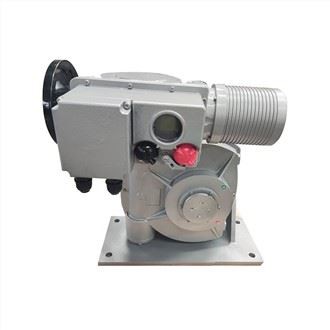
DQW electric actuator are suitable for butterfly valves, ball valves, plug valves and other rotary valves and similar equipment. The product has compact structure, large starting torque, high control precision, complete functions, reliable performance and convenient installation and adjustment. DQ is superimposed (DZW type plus secondary reducer) / DQJ is an electric actuator with lever angular travel of bearings and dampers. It cooperates with the valve to form an electric valve for driving and controlling the opening and closing of the valve. The operator can control the valve over long distances in the control room or on site. This product is widely used in water supply and drainage, heating, power station, chemical, food, textile, paper, pharmaceutical, shipbuilding, steel, coal and other industrial sectors.
According to the use environment: DQW / DQJW is outdoor type, DQB / DQJB is explosion-proof type, DQZ / DQJZ is integral type, DQT / DQJT is integral adjustment type, DQBZ / DQJBZ is full explosion-proof type, DQBT / DQJBT explosion-proof overall adjustable type. Torque range: 100N.m - 165000N.m
DQ is superimposed (DZW type plus secondary reducer) / DQJ is an electric actuator with lever angular travel of bearings and dampers. It cooperates with the valve to form an electric valve for driving and controlling the opening and closing of the valve. The operator can control the valve over long distances in the control room or on site. This product is widely used in water supply and drainage, heating, power station, chemical, food, textile, paper, pharmaceutical, shipbuilding, steel, coal and other industrial sectors.
Working principle
The part-turn electric valve actuator is composed of a DZW multi-turn electric valve actuator and a worm gear box. Its working principle is as follows:
Transmission system
This device is composed of a DZW electric valve actuator and a worm gear box. The DZW electric actuator is a first-stage worm gear box. The power is output by the valve motor, and is transmitted to the cam and clutch through the A and B gears through the worm. The first-stage output shaft then drives the worm gear pair of the rgearbox through the coupling for secondary deceleration. The final output speed is 3/10rpm~9/14rpm, that is, the valve is fully closed or fully opened for 23~50s at 90 degrees. The structure of the secondary gearbox is a fan-shaped worm gear structure, and then the output is output through the crank. The crank and the final output shaft are splined for easy on-site installation and commissioning.
Manual-electric switching mechanism
Push the switching handle to the limit position according to the rotation direction indicated on the sign, the clutch will disengage from the electric power and engage with the handwheel. Rotate the handwheel clockwise to directly turn the valve disc to the fully closed position.
Opening indication and stroke control mechanism
The pointer and switch mark indicating the valve disc opening of this actuator are installed on the shell of the secondary gearbox, so the switch position of the valve disc can be directly observed. The stroke control mechanism (counter) is installed in the control box, which can be used to adjust the number of revolutions of the output shaft of the DZW electric valve actuator, so as to achieve the purpose of controlling the size of the valve disc opening. The opening range is 0°~90°.
Mechanical limit and torque limiting mechanism
The mechanical limit mechanism of the gearbox uses two limit screws to limit the two sides of the fan-shaped worm wheel respectively, limiting the rotation angle of the worm wheel within a certain rotation angle range. When the electric actuator is running, once the stroke control mechanism fails, the worm wheel will rotate to the limit position, and its side will press against the limit screw, then the torque will increase, forcing the torque control mechanism to operate, thereby cutting off the power supply.


1. Gearbox worm (sector) worm gear pair
2. Opening pointer
3. Connecting screw
4. Control box
5. Travel control mechanism
6. Torque limiting mechanism
7. DZW electric actuator worm gear pair
8. Travel transmission bevel gear pair
9. Manual-to-electric clutch
10. Handwheel
11. Switching handle
12. A, B gear pair
13. Valve motor
14. DZW electric valve actuator
15. Coupling 16. Mechanical limit
17. Connecting plate
18. Gearbox
Installation and Adjustment
Installation
This electric valve actuator is adjusted to the fully closed state of the valve (i.e. the "closing direction mark" position) before leaving the factory, so the valve disc should be placed in the fully closed state before installing the valve, and then fixed with the corresponding screws after installation. After installation, it can be used without further adjustment. DQW part-turn electric valve actuator, since the output shaft of the electric actuator rotates 90°, the control box observation window and opening pointer should be facing up during installation. In addition, refer to the space dimensions shown in the electric actuator outline drawing, and leave enough space near the pipeline to facilitate installation, construction, maintenance and repair.
Adjustment
Adjustment steps for electric valve actuator:
a. Turn the switching handle to the manual position, and manually operate the valve to make it fully closed (i.e., the closing position mark).
b. Open the control box cover and adjust the closing adjustment shaft of the stroke control mechanism (counter). Before adjustment, press down the middle push rod and turn it 90 degrees to disengage the transmission gear. Rotate the adjustment shaft in closing direction indicated by the counter sign to make the cam in closing direction move to press the button of the control switch. You can hear a "click" sound, then loosen the push rod to make the transmission gear mesh well. Use the same method to adjust the stroke in opening direction.
c. Adjust the torque control mechanism cam in closing direction to the required torque value (refer to the torque curve diagram of the certificate, generally adjusted near the rated value). The opening direction is also adjusted in the same way.
d. The mechanical limit mechanism has been adjusted before the whole machine leaves the factory, and the user does not need to adjust it during normal use. If the user needs to adjust the mechanical limit, the following steps should be followed: first, unscrew the sealing screw and the locking screw, and adjust the limit screw outward appropriately. Secondly, manually make the final control element fully closed. At this time, the opening pointer of the gearbox should be aligned with the "closing mark" position (if the opening pointer is not aligned with the "closing direction mark" position at this time, the power supply should be disconnected, the electric actuator should be disconnected from the valve, and the spline position between the output shaft sleeve and the worm gear of the gearbox should be adjusted to ensure that when the final control element is in the fully closed state, the opening pointer of the gearbox should be aligned with the "closing direction mark" position), adjust the limit screw until it cannot be screwed in, then turn the limit screw outward 2 turns, tighten the locking screw, and finally screw on the sealing screw. Use the same method to adjust the opening mechanical limit.

Applications


Hot Tags: dqw quarter-turn on-off electric valve actuator, China, manufacturers, suppliers, factory, buy, price, quotation, Motorized Butterfly Valve, 4 20ma Flow Control Valve, Explosion Proof Butterfly Valve Actuator, Quarter Turn Valve Actuators, High Torque Electric Actuator, Butterfly Valve Actuator