


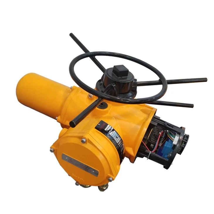


ELECTRIC ACTUATOR
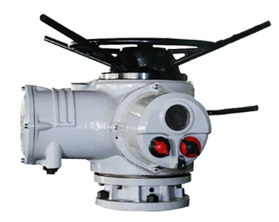
PRODUCT FEATURES
1. Continuously track valve position at all times, regardless of power supply.
2. Maintain normal operation and accessibility of graphical interface, remote indication and data logger after power loss.
3. Oil bath lubrication provides long life and the ability to be installed in any direction.
4. Waterproof protection that does not rely on terminal cover and interface seals - double seal structure, protection grade reaches IP68.
5. Independent torque and valve position sensors are used to greatly enhance safety performance.
6. The selection of remote manual control station can realize remote operation configuration and commissioning, with a maximum distance of up to 100 meters.
7. Safe, motor-independent handwheel device, which can be used at any time.
8. It provides detailed trend analysis and diagnostic data for asset management.
9. Upgrade configuration and change control and indication options on site through Bluetooth setter.
10. The screen can display real-time valve and actuator performance status information.
11. Quick and safe commissioning and configuration without power supply through non-invasive intrinsically safe Bluetooth setter.
12. Removable thrust base for easy installation and maintenance.
13. Explosion-proof options meet various international standards.
PRODUCT STRUCTURE
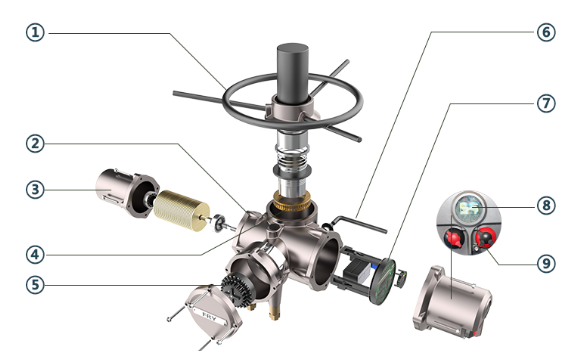

1.Handwheel
The sturdy handwheel provides reliable emergency manual operation in the event of power failure.
2. Shell
The high-quality aluminum alloy shell is compact and lightweight. It is coated with a layer of protective material to adapt to extremely harsh environments, and other types of layers are available as needed.
3. Motor
The low inertia and high torque motor allows the motor to quickly reach peak torque after starting, and there is almost no over-limit movement when it is off-excitation. There is a precise temperature switch embedded in the motor coil, which is not affected by the surrounding ambient temperature and keeps the motor in optimal thermal capacity. At the same time, the motor shaft and worm are independent of each other for quick replacement.
4. Worm gear
The worm gear transmission chain is simple, with exquisite structure and constant transmission efficiency. It has a mechanical self-locking function and does not require brakes. The transmission part is filled with long-lasting lubricating oil and can operate for a long time without maintenance.
5. Double-sealed design
The double-sealed design provides a sunflower terminal box that is separated from the control room and sealed. Even if the connection box cover is opened on site, it can ensure the isolation of the inside of the actuator from the outside world, so that moisture, dust, and hazardous gases cannot enter the actuator interior in the slightest, and the internal components are fully protected.
6. Manual/electric switch handle
The manual/electric switch handle can be operated safely at any time. While pressing the handle with appropriate force, slowly turn the handwheel to allow the internal clutch to engage the gear. The clutch will automatically disengage when the motor is energized and in the electrically locked state.
7. Output torque measurement system
A professionally designed useful power measurement system is used as the output torque measurement system. This system is developed from familiar electric energy measurement technology and can obtain accurate and repeatable torque measurement values that are independent of changes in frequency, voltage and temperature.
8. Control panel
The control panel LCD can provide instantaneous, up-to-date status and valve position, with Chinese and English languages available, using an intuitive menu structure to provide calibration and diagnostic information, including torque curves, operation and fault records, motor status, local information and hardware data, etc.
9. Button
The local control "Open"/"Close" buttons and the padlocked "Local"/"Stop"/"Remote" mode buttons all use isolated magnetic transmission Hall effect devices, with no through-shafts and good sealing performance, while eliminating the trouble that can be caused by faulty and fragile reed switches.
APPLICATIONS

WHAT IS A EXPLOSION PROOF TYPE ELECTRIC ACTUATOR?
Zones - Explosion groups - Temperature classes
Implementation
Areas with potentially explosive atmospheres are divided into zones, equipment has to be divided into groups and categories. The labelling on the identification plate of certified equipment indicates in which zone the explosion protected equipment can be used.
Division into product groups
Equipment is divided into group I and group II. Group I consists of underground mines and group II deals with all other applications.
Division into zones
Areas with potentially explosive atmospheres are divided into six zones according to the probability of how frequent and for which period of time a potentially explosive atmosphere (p.e.a.) exists.
A distinction is made between combustible gases, mists, vapors and combustible dust. For gases, mists and vapors zones 0, 1 and 2 exist, in which the requirements for the chosen equipment increase from zone 2 to 0. Equipment in zone 0 must be built in a way "that even if a type of protection fails or if two faults occur, that sufficient explosion protection is guaranteed". Therefore for example a passive, potential free sensor, installed in zone 0, and connected to an intrinsically safe electric circuit (II 2 (1) G [Ex ia] IIC), needs its own approval. Zones 20, 21 and 22 are for dust atmospheres, in which the requirements for the chosen equipment increase from zone 22 to 20. Equipment in zone 20 and 21 need special approval.
Example: Spray room with Ex zones, air handling system and Schischek Ex-proof components

Example: Filling station with Ex zones (Hazardous locations)

DIVISION INTO EQUIPMENT GROUPS
Equipment groups determine, in which zones the equipment may be installed. Once again there are six categories. Categories 1G, 2G and 3G are classifications for gas explosion protection (G = Gas); thereby 1G equipment is suitable for use in zones 0, 1 and 2, 2G equipment is suitable for use in zones 1 and 2 and 3G equipment is suitable for use in zone 2. Categories 1D, 2D and 3D are classifications for dust explosion protection (D = Dust); thereby 1D equipment is suitable for use in zones 20, 21 and 22, 2D equipment is suitable for use in zones 21 and 22 and 3D equipment is suitable for use in zone 2.
Division into explosion groups
Explosion protected equipment for gases, mists and vapors is divided into three explosion groups (IIA-IIB-IIC) according to the type of protection being used. The explosion group is a means to measure the ignitability of gases (potentially explosive atmos- pheres). The equipment requirements increase from IIA to IIC.
Division into temperature classes
Explosion proof equipment, installed within an Ex area, is divided into 6 temperature classes (T1 to T6). The temperature class is not – as it is often wrongly believed – the operating temperature range of the equipment, but the maximum permissible surface temperature of the equipment, in relation to + 40°C ambient temperature on any surface area, which may not be exceeded at any time. The maximum surface temperature must remain below the ignition temperature of the surroun-ding medium at all times. The equip-ment design requirements increase from T1 to T6.
HOW TO ACHIEVE EXPLOSION-PROOF?
The explosion-proof electric actuator must be produced in accordance with the ISO 9001 quality system standard. The explosion-proof function is designed and produced in accordance with the national electrical explosion-proof standards GB3836.2 (gas explosion-proof) and GB12476 (dust explosion-proof) and has passed explosion-proof certification. Domestic must obtain: "China National Compulsory Product Certification", "Explosion-proof Certificate", and foreign export also need to obtain relevant explosion-proof certification: "IECEX", "ATEX", "Customs Union CU-TR Explosion-proof Certification".
This type of explosion-proof electric actuator can withstand the internal explosion of a flammable mixture that has entered the interior of the housing without damage, and will not ignite through any joints or holes in the housing by one or more gases or vapors The enclosure of electrical equipment that forms an external explosive atmosphere.
The explosion-proof level of FRY explosion-proof series electric actuator is: ExdⅡBT4Gb
Ex - Explosion proof identification
D - Explosion Proof or Explosion Proof - Equipment type represents electrical equipment designed for explosive gas atmospheres other than coal mines
B - the size of the explosion, which determines the dimensions (width and clearance) of each fire joint of the actuator;
T4 - Temperature class represents the maximum allowable surface temperature of the actuator of 135°C
Gb - Protection class standard
CLASSIFICATION OF EXPLOSION-PROOF ELECTRICAL EQUIPMENT
Intrinsically safe electrical equipment:
Electrical equipment whose all circuits are intrinsically safe circuits is called intrinsically safe electrical equipment. The so-called intrinsically safe circuit refers to a circuit that cannot ignite an explosive mixture under specified conditions, under normal operation or under specified fault conditions, by generating sparks and thermal effects. The symbol of this type of equipment is "i" (divided into ia, ib).
Increased safety electrical equipment:
High-temperature electrical equipment that does not produce arcs, sparks, or the possibility of igniting explosive mixtures under normal operation, with measures taken in its construction to improve safety to avoid arcs, sparks, or the possibility of igniting explosive mixtures under normal or prescribed overload conditions The electrical equipment is called increased safety electrical equipment. This type of equipment is marked with an "e".
Explosion proof electrical equipment:
Electrical equipment with flameproof enclosures is called flameproof electrical equipment. The flameproof shell can not only withstand the explosion pressure generated by the detonation of the internal mixed gas, but also prevent the internal explosion flame and high temperature gas from breaking out of the flameproof gap to ignite the explosive mixture around the shell. This type of equipment is marked with a "d".
The explosion proof electric actuator produced by our company is designed to prevent the internal spark or the explosion carrier from contacting the outside through the flameproof surface of the shell. Face width (12.5mm-25mm) to ensure this. In addition, the joint surfaces of each component, such as the number of thread turns, thread accuracy, zero point, between screws, finger windows and the housing, between the motor and the output port, the gap between the components and the components, and the wire port, etc., are all explosion-proof Design is required so that the high pressure generated by the internal explosion will not damage the actuator.
SPARES FOR ELECTRIC ACTUATOR
Control Panel/Control Board


Encoder

Display Unit/Remote/Local/Knob

Output shaft

ELECTRIC VALVES


DESIGN FEATURES
1. Convenient and safe commissioning configuration
• Fast and safe commissioning configuration, which can be performed without power supply; multi-language human-machine interactive display is provided
• Non-intrusive settings can be performed in any environment
• Detachable thrust base for easy installation and maintenance of valves
• Operation, configuration and commissioning through remote manual control station, with a maximum distance of 100 meters
• Part-turn actuator provides automatic limit setting function
2. Technological advancement
• Position: The latest patented absolute encoder. The encoder adopts a non-contact design and has redundancy and self-detection capabilities. • Display: The advanced double-layer display provides users with large-character valve position display
• Torque: The actuator uses torque sensing technology
• Control: Control elements such as mainboards or bus control boards, actuators and fieldbus communications, use a bus-based internal communication system. This not only reduces wiring and internal connections but also increases reliability.
3. Reliability
• Advanced absolute position measurement to detect real-time continuous position without power
• Graphical interface, remote indication and data logger function after loss of main power
• Dustproof and waterproof, and does not rely on terminal cover and gland - double seal structure, protection level up to IP68
• Independent torque and valve position sensor
• Handwheel operation is safe and always independent of the motor
• Drive shaft bushing uses sealed bearings - maintenance-free
4. Asset management
• Screen can display real-time information of valves and actuators
• Safe and reliable data download through intrinsically safe setting tool
• Upgrade and configure control and indication in the field through setting tool
• Compatible with digital control and monitoring systems and other fieldbus systems
• Detailed trend analysis, diagnostics and data logging can be displayed on the screen or downloaded through the setting tool
5. Optimal preventive maintenance
• Actuators are equipped with a precision data logger that can provide data capture and analysis for valve position.
6. Indication power supply
• Because of the use of absolute encoder, no display battery is required to sense and track valve position. All settings are safe even without power.
7. Safe manual operation
8. Remote field operation
• Use standard data cable, the maximum distance from the actuator is 100 meters
• It can be mounted on a wall or bracket
• Powered by the connected actuator
• Optional explosion-proof type
• Protection grade IP68
• Double seal structure
• Simple setting
• Actuator data records can be displayed and downloaded locally
9. Temperature protection
• In order to prevent the motor from overheating, we have equipped the motor winding with a temperature sensor to directly sense the motor temperature and connect it to the actuator control circuit.
10. Automatic self-diagnosis
11. Instantaneous reversal protection
12. Phase synchronization
13. Valve blockage protection
14. Configurable main interface
• Valve position information and status
• Valve position information and torque value (digital)
• Valve position information and torque value (analog image)
• Valve position information and command information (digital or analog image)
PRODUCT DISPLAY

TECHNICAL PARAMETERS
FRYQ single-phase actuator performance parameters (220V 50Hz)
|
Model |
Output speed ( RPM) |
Output torque (NM) |
Motor power (KW) |
Rated current (A) |
|
FRYQ18 |
18 |
55 |
0.2 |
3.3 |
|
24 |
50 |
0.2 |
3.3 |
|
|
36 |
40 |
0.2 |
3.3 |
|
|
48 |
35 |
0.9 |
3.3 |
|
|
FRYQ25 |
18 |
210 |
0.9 |
9 |
|
24 |
210 |
0.9 |
9 |
|
|
36 |
170 |
0.9 |
9 |
|
|
48 |
130 |
1.1 |
9 |
|
|
FRYQ35 |
18 |
300 |
1.1 |
14 |
|
24 |
300 |
1.1 |
14 |
|
|
36 |
220 |
1.1 |
14 |
|
|
48 |
160 |
0.2 |
14 |
FRYQ three-phase actuator performance parameters (380V 50Hz)
|
Model |
Rotating speed ( RPM) |
Output torque (NM) |
Motor power (KW) |
Rated current (A) |
Rated trust (KN) |
Rising and non rising stem diameter (MM) |
Flange code |
Weight (KG) |
|
FRYQ18 |
18 |
136 |
0.37 |
1.6 |
44 |
32/26 |
F10 |
27 |
|
24 |
108 |
|||||||
|
36 |
72 |
|||||||
|
48 |
54 |
|||||||
|
FRYQ25 |
18 |
400 |
1.1 |
3.4 |
100 |
38/32 |
F14 |
46 |
|
24 |
400 |
|||||||
|
36 |
298 |
|||||||
|
48 |
244 |
|||||||
|
FRYQ35 |
18 |
610 |
1.5 |
4.5 |
150 |
54/45 |
F16 |
69 |
|
24 |
610 |
|||||||
|
36 |
542 |
|||||||
|
48 |
474 |
|||||||
|
FRYQ40 |
18 |
1020 |
2.2 |
6.5 |
220 |
64/51 |
F25 |
190 |
|
24 |
1020 |
|||||||
|
36 |
845 |
|||||||
|
48 |
680 |
|||||||
|
FRYQ70 |
18 |
1490 |
3 |
9 |
220 |
70/57 |
F25 |
190 |
|
24 |
1490 |
|||||||
|
36 |
1290 |
|||||||
|
48 |
1020 |
|||||||
|
FRYQ90 |
18 |
2030 |
5.5 |
14 |
334 |
70/57 |
F25 or F30 |
200 |
|
24 |
2030 |
|||||||
|
36 |
1700 |
|||||||
|
48 |
1355 |
|||||||
|
FRYQ95 |
24 |
3000 |
7.5 |
19 |
445 |
- |
F30 |
200 |
DIMENSIONS
FRYQ18-FRYQ40

FRYQ70-FRYQ95

FRYQ18-FRYQ40 dimensions
|
Model |
A |
B |
C |
D |
E |
F |
G |
H |
I |
|
FRYQ18 |
299 |
258.5 |
150 |
170 |
φ300 |
302 |
257 |
40 |
557.5 |
|
FRYQ25 |
328 |
357 |
150 |
248 |
φ642 |
333 |
278.5 |
40 |
685 |
|
FRYQ35 |
342 |
356 |
150 |
220 |
φ780 |
374 |
300 |
40 |
698.5 |
|
FRYQ40 |
502 |
479 |
195 |
290 |
φ812.5 |
515 |
351 |
40 |
979
|
FRYQ flange dimensions
|
Model |
D |
D1 |
D2 |
d1 |
d2 |
d Well distributed |
h |
H1 |
f |
b |
|
FRYQ18 |
φ145 |
φ120 |
φ90 |
φ30.5 |
φ45 |
4-M10 |
11 |
2 |
5 |
23.5 |
|
FRYQ25 |
φ185 |
φ160 |
φ125 |
φ43 |
φ58 |
4-M12 |
9.5 |
2.5 |
5 |
25 |
|
FRYQ35 |
φ225 |
φ195 |
φ150 |
φ51.5 |
φ72 |
4-M26 |
12 |
2 |
5 |
24 |
|
FRYQ40 |
φ275 |
φ235 |
φ180 |
φ62 |
φ83 |
4-M22 |
14 |
2 |
5 |
21 |
|
FRYQ70-95 |
φ330 |
φ285 |
φ220 |
φ72 |
φ98 |
4-M26 |
16 |
2 |
6 |
30 |
FACTORY PICTURES

Hot Tags: exdiict4 explosion-proof intelligent electric actuator, China, manufacturers, suppliers, factory, buy, price, quotation, Electric Actuator For Rotork


