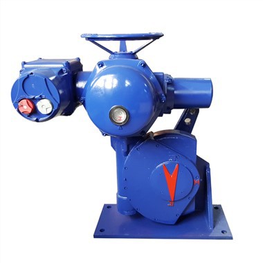


Floating control HVAC Electric Linear Actuator

OVERVIEW
The electric control valve consists of an electric actuator and a valve body. Driven by electric power, it completes valve opening, closing and medium throttling automatically. It is widely applied in industrial pipelines for water, oil, steam and gas media. Compared with manual valves, it removes the need for on‑site manual operation. It supports both local on‑site control and remote system control, which realizes automatic pipeline flow cut‑off and flow adjustment. Equipped with emergency manual override structure, the valve can be operated manually when power fails. With reliable sealing performance and stable throttling capability, it adapts to various working conditions of chemical, water treatment, heating, petroleum and general industrial systems.
FEATURES OF ELECTRIC ACTUATORS
• Compact and robust construction, lightweight.
• Wide range of torque variation.
• Hard anodized aluminum housing inside and outside with external high temperature paint coating for use against severe industrial environment.
• Enclosure uses radial seals & O-rings that provide protection to waterproof IP68.
• It automatically identifies and corrects phases. Automatic phase failure protection protects equipment safety.
• Reliable mechanical torque sensing system providing safe operation in overload condition.
• Large size window and indicator provides better position indication from a distance.
• Number of local position control options to provide easy commissioning and field operation.
PRODUCT ADVANTAGES
Diversified needs
The process technology sites of supporting pipelines and automated valves are all over the world. Not only the site and valve type are important factors in the selection of electric actuators, but also the climate environment of on-site operation is crucial. FRY-A electric actuators guarantee safe and reliable service under various extreme environmental conditions.
Superior performance
Quality Assurance
Only when all on-site equipment provides reliable service throughout its entire life can the entire process site be efficient, economical and safe.
Long warranty period
MAIN FUNCTIONS
Explosion Proof
Based on your specific hazardous area classification and medium type (Group IIA/IIB/IIC gases or dusts), custom-engineer explosion-proof Electric control valve consists of an electric actuatorthat fully comply with international and domestic standards, including IECEx, ATEX, and GB 3836.

Colors
You can provide your own color code or choose special coatings for corrosion resistance, weather resistance, or high-temperature warning. Using advanced spraying technology and high-quality coatings, we ensure a durable, uniform finish. This gives your equipment a personalized look while maintaining long-term durability in industrial environments.

Protection grade
Based on your installation environment - outdoor rain, coastal salt spray, desert dust, or food/pharma workshops needing high-pressure washing. We provide sealing solutions from basic dust/water protection (IP65/IP67) to ultra-high protection (IP68/IP69K).

Low-temperature
For the specific operating conditions in extremely cold regions, we offer professional, deeply customized low-temperature environment services for Manual Worm‑gear PTFE‑Lined Butterfly Valve . By employing special low-temperature resistant materials, wide-temperature-range lubricants, and intelligent heat tracing systems, we ensure that the equipment can reliably start and operate accurately even in extremely low-temperature environments. We also comprehensively optimize the cold resistance of seals, electronic components, and display screens to effectively prevent problems such as lubrication freezing, sluggish displays, or start-up failures caused by low temperatures.

Wiring

Illustrate :
1. Pos:feedback signal
2. Y :Input signal
Floating type:
*In floating control mode, S2-8 DIP switch is set to ON. the input signal (Y) will be invalid.
Dimension(mm)


Function Operation Instructions
Manual operations
The ML8824 series actuator can be operated manually using the supplied hexagon wrench and features a manual override function. For safety reasons, the actuator automatically cuts off the power supply to the motor when manual operations are performed.
Note: The self-adaption process must be repeated after completing manual operations when the actuator is switched off!
Rotate the hexagon wrench clockwise to shift the actuator connector downwards; rotate anticlockwise to shift the actuator connector upwards.
Enabling floating control
The ML8824 series actuator features a floating control function (see wiring diagram, page 5).When the S2-8 DIP switch on the PCB is set to ON (see Table of DIP Switch Settings, page 6),this indicates that floating control is enabled and the actuator will travel to the fully open or fully closed position without being controlled by the input signal (0/2–10VDC, 0/4–20mA).This ensures that manual operations can be completed safely.
Input /feedback signal
The analog input/feedback signal can be selected using the DIP switch (see Table of DIP Switch Settings). The default input/feedback signal is 0...10 Vdc. You can select 2–10VDC, 0–20mA and 4–20mA input/output signals using the DIP switches on the PCB.
Wiring
The actuator comes with a pre-assembled PG13.5 cable gland, with spaces reserved for PG13.5 and PG9 connectors.
Note: To prevent the actuator from malfunctioning, connect it to a 24 V/AC power supply with a ground connection (see wiring diagram).
Self-adaption mode
Assemble the actuator and the valve and power the actuator with a 24 VAC/DC power supply.
Automatic self-adaption: The actuator will automatically enter self-adaption mode when it is supplied with power. The yellow indicator light on the PCB will blink (1Hz) and the actuator will fully close (travel to the lowest position) and then fully open (travel to the highest position). The indicator light will stop blinking when the self-adaption process is complete. The actuator will then travel to the position designated by the control signal.
Manual self-adaption: To enable self-adaption mode, press and hold the S1 button on the PCB for at least 5 seconds (see PCB Layout Diagram) until the indicator starts blinking (1Hz).The actuator will fully close (travel to the lowest position) and then fully open (travel to the
highest position). The indicator light will stop blinking when the self-adaption process is complete. The actuator will then travel to the position designated by the control signal.
Note: Travel calibration takes approximately 3 minutes for the 600 N actuator and approximately 4 minutes for the 1800 N actuator (when the default settings are enabled).
Actuator operating mode when input signal is interrupted
Use No. S2-9 DIP switch (see Table of DIP Switch Settings) to set actuator operation mode as the first step when input signal is interrupted. If the DIP switch is ON, actuator will keep the position when the input signal is interrupted. If the DIP switch is OFF, actuator will reset when the input signal is interrupted.Selecting actuator resetting requires the second step of signal interruption mode setting: setting the S2-6-digit DIP switch.
No. S2-6 DIP switch is ON: when the controlling input signal is interrupted, if the input signal is a voltage signal, the actuator will automatically generate a 0(2) V/DC input signal; If the input signal is a current signal, the actuator will automatically generate a 0 (4) mA input signal.
(factory default)
No. S2-6 DIP is OFF: when the controlling input signal is interrupted, if the control signal is a voltage signal, the actuator will automatically generate a 10 V/DC input signal; if the input signal is a current signal, the actuator will automatically generate a 0 (4) mA input signal.
Note: 1. The setting of DIP No. S2-9 takes priority over DIP No. S2-6.
2. The actuator keeps the position when input signal is interrupted is limited to input signal and feedback signal are 4-20mA.
Setting the direction of travel
The direction of travel can be configured using the S2-5 DIP switch (see Table of DIP Switch Settings, page 6).
When the DIP switch is set to ON and the input signal is set to 0(2) VDC or 0(4) mA, the actuator will travel to the highest position.
When the DIP switch is set to OFF and the input signal is set to 0(2) VDC or 0(4) mA, the actuator will travel to the lowest position (factory default).
DIP Setting

|
S2-1 |
Setting start point of control/feedback signal |
ON |
4-20 mA or 2-10 V/DC control/feedback signal |
|
OFF |
0-20 mA or 0-10 V/DC control/feedback signal (factory default) |
||
|
S2-2 |
Setting type of control signal |
ON |
II: Current control |
|
OFF |
UI: Voltage control (factory default) |
||
|
S2-3 |
Setting input impedance matching of control signal |
ON |
UI: Control signal is voltage signal (factory default) |
|
OFF |
II: Control signal is current signal |
||
|
S2-4 |
Setting type of valve position feedback signal |
ON |
IO: Current feedback signal |
|
OFF |
UO: Voltage feedback signal (factory default) |
||
|
S2-5 |
Set the operating mode |
ON |
DA: When the control signal increases, the actuator moves downwards. When the control signal decreases, the actuator moves upwards. |
|
OFF |
RA: When the control signal increases, the actuator moves upwards. When the control signal decreases, the actuator moves downwards. (Factory default) |
||
|
S2-6 |
Set signal mode for actuator reset operation when input signal is interrupted |
ON |
DW: When the control signal is a voltage or current signal, the actuator will automatically generate a minimum control signal if the input signal cable is cut (factory default). |
|
OFF |
UP: 1) When the control signal is a voltage signal, the actuator will automatically generate a maximum control signal if the input signal cable is cut. 2) When the control signal is a current signal, the actuator will automatically generate a minimum control signal if the input signal cable is cut. |
||
|
S2-7 |
Set self-adaption mode |
ON |
DF: Power-on self-adaption mode (factory default). |
|
OFF |
RF: Manual self-adaption mode |
||
|
S2-8 |
Set control mode |
ON |
Floating control |
|
OFF |
Modulating control (factory default) |
||
|
S2-9 |
Actuator operating mode when input signal is interrupted |
ON |
Actuator keeps the position when input signal is interrupted. Notes: only for input signal and feedback signal are 4-20mA. |
|
OFF |
Actuator reset when input signal is interrupted and need to set No. S2-6 DIP switch together. Note: 1. The setting of DIP No. S2-9 takes priority over DIP No. S2-6. (factory default) |
||
|
S2-10 |
Speed setting |
ON |
High speed: 600 N (3 s/mm), 1800 N (2 s/mm) |
|
OFF |
Low speed: 600 N (4 s/mm), 1800 N (3 s/mm) (factory default) |
NFC Setting
1. Language selection
Enter the APP interface, click the menu icon in the upper right corner to set the language.
2. Parameter reading
Use the mobile phone to approach the "NFC" area of the actuator, and the interface will display "read successfully" to read the model, current opening, dead zone and sensitivity of the actuator.
3. Parameter setting In the parameter setting interface, activate the advanced parameter setting, and you can set the three parameters of dead zone, sensitivity and maximum opening. After setting, put the mobile phone close to the "NFC" area of the actuator, and the APP interface will display "write success", indicating that the set parameters have been successfully written into the actuator. Put the mobile phone close to the "NFC" area of the actuator again, and the set parameters can be Read.
Technical Parameters
|
SKU (Standard) |
ML8824A0620 |
ML8824A1820 |
ML8824A1840 |
|
SKU (NFC) |
ML8824B0620 |
ML8824B1820 |
ML8824B1840 |
|
Thrust Force |
≥600N |
≥1800N |
≥1800N |
|
Stroke |
26mm |
26mm |
46mm |
|
Running time |
3s/mm or 4s/mm |
2s/mm or 3s/mm |
2s/mm or 3s/mm |
|
Power Consumption |
10VA |
18VA |
18VA |
|
Power Supply |
24Vac ± 15%, 50/60Hz; 24Vdc +15%, -10% |
24Vac ± 15%, 50/60Hz; 24Vdc +15%, -10% |
24Vac ± 15%, 50/60Hz; 24Vdc +15%, -10% |
|
Input Signal |
0(2)~10 Vdc, 0(4)~20 mA |
0(2)~10 Vdc, 0(4)~20 mA |
0(2)~10 Vdc, 0(4)~20 mA |
|
Feedback Signal |
0(2)~10 Vdc, 0(4)~20 mA |
0(2)~10 Vdc, 0(4)~20 mA |
0(2)~10 Vdc, 0(4)~20 mA |
|
Operation Environment |
-10℃ to +55℃, 5% to 95% RH (Non-condensing) |
-10℃ to +55℃, 5% to 95% RH (Non-condensing) |
-10℃ to +55℃, 5% to 95% RH (Non-condensing) |
|
Storage Environment |
-40℃ to +65℃, 5% to 95% RH (Non-condensing) |
-40℃ to +65℃, 5% to 95% RH (Non-condensing) |
-40℃ to +65℃, 5% to 95% RH (Non-condensing) |
|
Available Medium Temperature |
Water: up to 130℃; Steam: up to 180℃ |
Water: up to 130℃; Steam: up to 180℃ |
Water: up to 130℃; Steam: up to 180℃ |
|
Protection Class |
IP54 (EN60730) |
IP54 (EN60730) |
IP54 (EN60730) |
|
Electrical Protection Class |
III (EN60730-1) |
III (EN60730-1) |
III (EN60730-1) |
|
Certification |
CE (EN60730) |
CE (EN60730) |
CE (EN60730) |
|
Wiring Terminals |
1.5mm² |
1.5mm² |
1.5mm² |
|
Cable Connector |
PG13.5, Reserved PG13.5 and PG9 |
PG13.5, Reserved PG13.5 and PG9 |
PG13.5, Reserved PG13.5 and PG9 |
|
Material |
Cover: PC Plastic; Housing: Plastic; Bracket: Cast aluminum |
Cover: PC Plastic; Housing: Cast aluminum; Bracket: Cast aluminum |
Cover: PC Plastic; Housing: Cast aluminum; Bracket: Cast aluminum |
|
Weight |
1.3kg |
2.3kg |
2.4kg |
COMPANY INTRODUCTION
Founded in 2014, Freya mainly deals in valves, actuators, electric valve actuators, electric valves and other fluid control products and services. It focuses on the process industry field and has long been committed to providing professional fluid control solutions for process industries such as electricity, steel, building materials, and water treatment. According to actual working conditions, through necessary field surveying and technical disclosure, it provides customers with safe, economical, and environmentally friendly selection and design, strictly supplies and guides installation and commissioning in accordance with contract requirements, and hands over for use when the standards are met. The company has always focused on improving its innovation capabilities, and has achieved a series of innovative results by increasing R&D investment and introducing technology. In the past few years, the company has successfully applied for non-invasive appearance patents and utility model patent certificates. These innovative achievements have improved the company's core competitiveness.
APPLICATIONS

CERTIFICATES


Hot Tags: floating control hvac electric linear actuator, China, manufacturers, suppliers, factory, buy, price, quotation