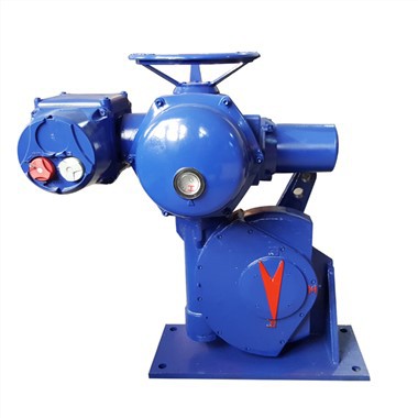


MULTI-TURN ELECTRIC ACTUATOR

The FRYPB series electric actuators feature an aluminum alloy housing, offering a wide operating temperature range and a high protection rating. Supporting multiple control modes and communication protocols, they incorporate comprehensive protection mechanisms and a vibration-resistant design. Certified to various international standards, these cost-effective products are ideal for industrial automation control in demanding operating environments.
FEATURES OF ELECTRIC ACTUATORS
This series of electric valve actuators features the following characteristics:
• Compact, robust, and lightweight design.
• Wide torque range.
• Aluminum alloy housing treated with hard anodizing (both internally and externally) and a high-temperature resistant exterior coating, suitable for harsh industrial environments.
• IP68 protection rating (waterproof).
• Equipped with multiple protection functions-including over-temperature, over-current, and motor stall protection-to ensure equipment safety.
• Utilizes programmable relays, high-precision non-contact sensors, and limit switches to ensure safe operation.
• Features a 360° visible position indicator and a 360° visible remote position indicator light for easy monitoring of valve position.
• Offers various local control options to facilitate commissioning and on-site operation.
PRODUCT ADVANTAGES
Diversified needs
The EPB series electric actuators are designed for harsh operating conditions, featuring a wide temperature range, high ingress protection, and robust vibration resistance. They support flexible networking through integrated control modes and communication protocols, while ensuring operational reliability via multiple safety protections, an exceptionally long service life, and authoritative international certifications-making them a premier choice for industrial automation that balances high performance with cost-effectiveness.
Superior performance

Quality Assurance
Only when all on-site equipment operates reliably throughout its entire lifecycle can the overall production process be efficient, cost-effective, and safe. Rated for 50,000 cycles (0-90-0) and 5,000,000 starts (modulating duty).
Long warranty period

MAIN FUNCTIONS
Protection class
IP67 (Standard)
IP68 (Optional)
NEMA 4/4P/6/6P (Optional)
Surface anti-corrosion coating
ISO 12944 C3-02 (Standard)
ISO 12944 C3-C5 (Optional)
Control Mode
Standard On/Off
Smart On/Off
Smart Modulating
Bus-based
Timer-based (Custom)
Seismic Resistance
Standard Seismic Resistance (Standard)
5–1200 Hz, 1.5g, 48 hours (X, Y, and Z axes)
Enhanced Seismic Resistance (Optional)
5–50 Hz, 5g, 5 hours (X, Y, and Z axes)
Simulated Earthquake Resistance (Optional)
10g, 13ms pulse width, 125 shocks (X, Y, and Z axes)
Feedback signal method
Programmable relay
High-precision non-contact sensor
Limit switch

CONTROL MODE
External control
All actuator signals, such as limit switch signals, torque switch signals, motor thermal protection and valve position, can be transmitted to the external control device for further processing. When designing the control logic architecture, it is necessary to fully consider the necessary protection mechanisms and minimize the delay time.The contactor device used to control the operation of the motor is installed in the external control device and connected to the actuator via a cable.When a local control operation interface is required, the local control operation interface should be installed near the actuator and integrated with the external control device.
Integrated control
When the actuator is powered on, the actuator with integrated control unit can be operated by the operating elements of the local control. The control unit is fully adapted to the actuator. The actuator can be set up on site without connecting to the DCS system. Only the transmission and exchange of operating commands and feedback signals are required between the control system and the actuator. The on-off control of the motor is completed instantly in the device.
Fieldbus
The use of bus cables can save a lot of space in the control cabinet, and it is more obvious that the traditional input and output signal line connection is outdated. The use of two-core cables simplifies the commissioning phase and greatly reduces the cost of cables in the long-distance field.Another major advantage of fieldbus technology is the transmission of preventive maintenance and diagnostic information to the control room. Therefore, fieldbus technology integrates all fieldbus devices into the asset management system to support the safety protection measures of field device utilization. Actuators equipped with intelligent integrated control units can be applied to various common standard types of fieldbus systems in process automation.

STANDARD SPECIFICATIONS
|
Housing material |
Aluminum alloy |
|
Motor Type |
Brushless DC motor |
|
Operating temperature range |
-25°C to 65°C (standard)-40°C to 65°C (optional) |
|
Operating humidity range |
0%–95% |
|
Starting frequency |
IEC 60034-1 S1 100% |
|
Surface Anti-Corrosion Coating |
ISO 12944 C3-02 (Standard)ISO 12944 C3-C5 (Optional) |
|
Protection Functions |
Multiple over-temperature protections |
|
Over-current protection |
|
|
Motor stall protection |
|
|
Position indicator |
360° visible position indicator |
|
360° long-range visible position indicator light |
|
|
Ingress Protection Rating |
IP67 (Standard) |
|
IP68 (Optional) |
|
|
NEMA 4/4P/6/6P (Optional) |
|
|
Service Life |
50,000 cycles (0-90-0) |
|
5,000,000 starts (modulating type) |
|
|
Manual operation |
External hex wrench |
|
Hex key (Allen key) |
|
|
Handwheel |
|
|
(Operating method varies by model) |
|
|
Control Mode |
Standard On/Off |
|
Smart On/Off |
|
|
Smart Modulating |
|
|
Bus-based |
|
|
Timer-based (Custom) |
|
|
Feedback signal method |
Programmable relay |
|
High-precision non-contact sensor |
|
|
Limit switch |
|
|
Modulating input/output signals |
1–5 V |
|
2–10 V |
|
|
4–20 mA |
|
|
Potentiometer (custom) |
|
|
Communication Protocols |
Modbus-RTU |
|
PROFIBUS |
|
|
IO-Link |
|
|
AS-i |
|
|
Certifications |
CSA |
|
CE [TÜV] |
|
|
SIL2/3 [CSA] |
|
|
NEMA 6P [CSA] |
|
|
IP68 [SGS] |
|
|
RoHS [SGS] |
TECHNICAL DATA
|
model |
Torque |
90° |
Voltage Current |
AC24V |
DC24V |
AC110V |
AC220V |
AC380V |
AC440V |
|
|
Standard Series |
||||||||||
|
FRYPB20P1 |
10N·m |
89in-lb |
6s |
Rated current (A) |
0.8 |
0.45 |
0.18 |
0.1 |
× |
× |
|
Operating current (A) |
0.6 |
0.35 |
0.13 |
0.05 |
× |
× |
||||
|
Locked-rotor current (A) |
2.4 |
1.5 |
0.75 |
0.75 |
× |
× |
||||
|
FRYPB20P2 |
14N·m |
124in-lb |
8s |
Rated current (A) |
0.8 |
0.45 |
0.18 |
0.1 |
× |
× |
|
Operating current (A) |
0.6 |
0.35 |
0.13 |
0.05 |
× |
× |
||||
|
Locked-rotor current (A) |
2.4 |
1.5 |
0.75 |
0.75 |
× |
× |
||||
|
FRYPB20P3 |
20N·m |
177in-lb |
11s |
Rated current (A) |
0.8 |
0.45 |
0.18 |
0.1 |
× |
× |
|
Operating current (A) |
0.6 |
0.35 |
0.13 |
0.05 |
× |
× |
||||
|
Locked-rotor current (A) |
2.4 |
1.5 |
0.75 |
0.75 |
× |
× |
||||
|
FRYPB50P1 |
40N·m |
354in-lb |
8s |
Rated current (A) |
1.8 |
1.1 |
0.51 |
0.26 |
0.12 |
0.1 |
|
Operating current (A) |
1.2 |
0.7 |
0.36 |
0.18 |
0.06 |
0.05 |
||||
|
Locked-rotor current (A) |
3.75 |
3 |
1.5 |
0.95 |
0.3 |
0.25 |
||||
|
FRYPB50P2 |
60N·m |
531in-lb |
12s |
Rated current (A) |
1.8 |
1.1 |
0.51 |
0.26 |
0.12 |
0.1 |
|
Operating current (A) |
1.2 |
0.7 |
0.36 |
0.18 |
0.06 |
0.05 |
||||
|
Locked-rotor current (A) |
3.75 |
3 |
1.5 |
0.95 |
0.3 |
0.25 |
||||
|
FRYPB100P1 |
80N·m |
708in-lb |
16s |
Rated current (A) |
1.5 |
0.8 |
0.4 |
0.2 |
0.12 |
0.1 |
|
Operating current (A) |
1 |
0.5 |
0.3 |
0.13 |
0.06 |
0.05 |
||||
|
Locked-rotor current (A) |
3.75 |
3 |
1.5 |
0.95 |
0.3 |
0.25 |
||||
|
FRYPB100P2 |
100N·m |
885in-lb |
18s |
Rated current (A) |
1.8 |
1 |
0.5 |
0.26 |
0.12 |
0.1 |
|
Operating current (A) |
1.2 |
0.65 |
0.34 |
0.17 |
0.06 |
0.05 |
||||
|
Locked-rotor current (A) |
3.75 |
3 |
1.5 |
0.95 |
0.3 |
0.25 |
||||
|
FRYPB200P2 |
200N·m |
1770in-lb |
10s |
Rated current (A) |
6 |
4 |
1.7 |
0.9 |
0.55 |
0.5 |
|
Operating current (A) |
3.2 |
2 |
0.8 |
0.52 |
0.3 |
0.26 |
||||
|
Locked-rotor current (A) |
9.45 |
6 |
2.4 |
1.5 |
0.9 |
0.9 |
||||
|
FRYPB200P4 |
300N·m |
2655in-lb |
15s |
Rated current (A) |
6 |
4 |
1.7 |
0.9 |
0.55 |
0.5 |
|
Operating current (A) |
4 |
2.5 |
1 |
0.65 |
0.36 |
0.33 |
||||
|
Locked-rotor current (A) |
12 |
7.5 |
3 |
1.89 |
0.9 |
0.9 |
||||
|
FRYPB200P5 |
400N·m |
3540in-lb |
19s |
Rated current (A) |
6 |
4 |
1.7 |
0.9 |
0.55 |
0.5 |
|
Operating current (A) |
4 |
2.5 |
1 |
0.65 |
0.36 |
0.33 |
||||
|
Locked-rotor current (A) |
12 |
7.5 |
3 |
1.89 |
0.9 |
0.9 |
||||
|
FRYPB500P3 |
500N·m |
4425in-lb |
24s |
Rated current (A) |
7 |
5 |
1.8 |
1.1 |
0.55 |
0.5 |
|
Operating current (A) |
4.6 |
3.2 |
1.1 |
0.7 |
0.36 |
0.33 |
||||
|
Locked-rotor current (A) |
12 |
9.45 |
3.75 |
2.4 |
0.9 |
0.9 |
||||
|
FRYPB500P5 |
800N·m |
7080in-lb |
36s |
Rated current (A) |
7 |
5 |
1.8 |
1.1 |
0.55 |
0.5 |
|
Operating current (A) |
4.6 |
3.2 |
1.1 |
0.7 |
0.36 |
0.33 |
||||
|
Locked-rotor current (A) |
12 |
9.45 |
3.75 |
2.4 |
0.9 |
0.9 |
||||
|
FRYPB500P6 |
1000N·m |
8850in-lb |
38s |
Rated current (A) |
7.3 |
5.2 |
1.9 |
1.1 |
0.55 |
0.5 |
|
Operating current (A) |
5 |
3.5 |
1.2 |
0.7 |
0.36 |
0.33 |
||||
|
Locked-rotor current (A) |
12 |
9.45 |
3.75 |
2.4 |
0.9 |
0.9 |
||||
|
FRYPB500P7 |
1200N·m |
1062in-lb |
45s |
Rated current (A) |
7.3 |
5.2 |
1.9 |
1.1 |
0.55 |
0.5 |
|
Operating current (A) |
5 |
3.5 |
1.2 |
0.7 |
0.36 |
0.33 |
||||
|
Locked-rotor current (A) |
12 |
9.45 |
3.75 |
2.4 |
0.9 |
0.9 |
||||
|
FRYPB2000P2 |
1600N·m |
14160in-lb |
62s |
Rated current (A) |
7.5 |
5.2 |
2.1 |
1.1 |
0.55 |
0.5 |
|
Operating current (A) |
4.6 |
3.1 |
1.35 |
0.7 |
0.36 |
0.33 |
||||
|
Locked-rotor current (A) |
12 |
9.45 |
4.8 |
2.4 |
0.9 |
0.9 |
||||
|
FRYPB2000P3 |
2000N·m |
17700in-lb |
77s |
Rated current (A) |
7.5 |
5.2 |
2.1 |
1.1 |
0.55 |
0.5 |
|
Operating current (A) |
4.6 |
3.1 |
1.35 |
0.7 |
0.36 |
0.33 |
||||
|
Locked-rotor current (A) |
12 |
9.45 |
4.8 |
2.4 |
0.9 |
0.9 |
||||
|
FRYPB3000P1 |
2500N·m |
22125in-lb |
95s |
Rated current (A) |
7.5 |
5.2 |
2.1 |
1.1 |
0.55 |
0.5 |
|
Operating current (A) |
4.6 |
3.1 |
1.35 |
0.7 |
0.36 |
0.33 |
||||
|
Locked-rotor current (A) |
12 |
9.45 |
4.8 |
2.4 |
0.9 |
0.9 |
||||
|
FRYPB3000P2 |
3000N·m |
26550in-lb |
114s |
Rated current (A) |
7.5 |
5.2 |
2.1 |
1.1 |
0.55 |
0.5 |
|
Operating current (A) |
4.6 |
3.1 |
1.35 |
0.7 |
0.36 |
0.33 |
||||
|
Locked-rotor current (A) |
12 |
9.45 |
4.8 |
2.4 |
0.9 |
0.9 |
||||
|
Quick-Open Series |
||||||||||
|
FRYPB115 |
9N·m |
80in-lb |
5s |
Rated current (A) |
1.6 |
0.8 |
0.4 |
0.18 |
× |
× |
|
Operating current (A) |
1 |
0.6 |
0.3 |
0.15 |
× |
× |
||||
|
Locked-rotor current (A) |
2.4 |
1.5 |
0.75 |
0.75 |
× |
× |
||||
|
FRYPB215 |
23N·m |
204in-lb |
5s |
Rated current (A) |
1.5 |
0.9 |
0.44 |
0.24 |
0.11 |
0.09 |
|
Operating current (A) |
1 |
0.6 |
0.3 |
0.15 |
0.06 |
0.05 |
||||
|
Locked-rotor current (A) |
3.75 |
3.15 |
1.55 |
0.95 |
0.3 |
0.25 |
||||
|
FRYPB315 |
50N·m |
443in-lb |
5s |
Rated current (A) |
3.8 |
2.8 |
1 |
0.53 |
0.2 |
0.19 |
|
Operating current (A) |
2.4 |
1.6 |
0.63 |
0.35 |
0.15 |
0.14 |
||||
|
Locked-rotor current (A) |
7.5 |
4.8 |
1.89 |
0.95 |
0.6 |
0.5 |
||||
|
FRYPB415 |
80N·m |
708in-lb |
5s |
Rated current (A) |
2.9 |
1.9 |
0.85 |
0.45 |
0.22 |
0.17 |
|
Operating current (A) |
2.1 |
1.4 |
0.6 |
0.3 |
0.17 |
0.16 |
||||
|
Locked-rotor current (A) |
6 |
3.75 |
1.5 |
0.95 |
0.9 |
0.9 |
||||
|
FRYPB425 |
120N·m |
1062in-lb |
5s |
Rated current (A) |
3.8 |
2.7 |
1.1 |
0.6 |
0.3 |
0.26 |
|
Operating current (A) |
2.6 |
1.8 |
0.8 |
0.4 |
0.21 |
0.2 |
||||
|
Locked-rotor current (A) |
7.5 |
4.8 |
1.89 |
1.5 |
0.9 |
0.9 |
||||
|
FRYPB435 |
150N·m |
1328in-lb |
5s |
Rated current (A) |
4.6 |
3.1 |
1.3 |
0.7 |
0.34 |
0.31 |
|
Operating current (A) |
3.1 |
2.2 |
0.9 |
0.5 |
0.24 |
0.22 |
||||
|
Locked-rotor current (A) |
9.45 |
6 |
2.4 |
1.5 |
0.9 |
0.9 |
||||
|
FRYPB445 |
200N·m |
1770in-lb |
5s |
Rated current (A) |
6 |
4 |
1.7 |
0.9 |
0.42 |
0.39 |
|
Operating current (A) |
3.8 |
2.7 |
1.1 |
0.6 |
0.3 |
0.26 |
||||
|
Locked-rotor current (A) |
12 |
7.5 |
3 |
1.89 |
0.9 |
0.9 |
||||
|
FRYPB455 |
300N·m |
2655in-lb |
5s |
Rated current (A) |
8 |
5.7 |
2.3 |
1.2 |
0.6 |
0.54 |
|
Operating current (A) |
5.3 |
3.6 |
1.5 |
0.8 |
0.4 |
0.37 |
||||
|
Locked-rotor current (A) |
15 |
12 |
4.8 |
2.4 |
0.9 |
0.9 |
||||
|
FRYPB465 |
400N·m |
3540in-lb |
5s |
Rated current (A) |
10.5 |
7.6 |
3.1 |
1.6 |
0.78 |
0.7 |
|
Operating current (A) |
7.1 |
4.8 |
2 |
1 |
0.5 |
0.45 |
||||
|
Locked-rotor current (A) |
18.9 |
15 |
6 |
3 |
0.9 |
0.9 |
||||
|
FRYPB51A |
500N·m |
4425in-lb |
10s |
Rated current (A) |
6.5 |
4.5 |
1.9 |
0.95 |
0.5 |
0.42 |
|
Operating current (A) |
4 |
3 |
1.2 |
0.7 |
0.3 |
0.26 |
||||
|
Locked-rotor current (A) |
12 |
7 |
3.75 |
1.89 |
0.9 |
0.9 |
||||
|
FRYPB52A |
650N·m |
5753in-lb |
10s |
Rated current (A) |
8.2 |
5.7 |
2.4 |
1.2 |
0.6 |
0.54 |
|
Operating current (A) |
5.3 |
3.6 |
1.5 |
0.8 |
0.4 |
0.37 |
||||
|
Locked-rotor current (A) |
15 |
9.45 |
4.8 |
2.4 |
0.9 |
0.9 |
||||
|
FRYPB53A |
800N·m |
7080in-lb |
15s |
Rated current (A) |
6.5 |
4.5 |
1.9 |
0.95 |
0.5 |
0.42 |
|
Operating current (A) |
4 |
3 |
1.2 |
0.7 |
0.3 |
0.26 |
||||
|
Locked-rotor current (A) |
12 |
7.5 |
3.75 |
1.89 |
0.9 |
0.9 |
||||
|
FRYPB54A |
1000N·m |
8850in-lb |
15s |
Rated current (A) |
8.2 |
5.7 |
2.4 |
1.2 |
0.6 |
0.54 |
|
Operating current (A) |
5.3 |
3.6 |
1.5 |
0.8 |
0.4 |
0.37 |
||||
|
Locked-rotor current (A) |
15 |
9.45 |
4.8 |
2.4 |
0.9 |
0.9 |
||||
DIMENSIONS

PRODUCT DISPLAY

PRODUCT REAL SHOT

COMPANY INTRODUCTION
Founded in 2014, Freya mainly deals in valves, actuators, electric valve actuators, electric valves and other fluid control products and services. It focuses on the process industry field and has long been committed to providing professional fluid control solutions for process industries such as electricity, steel, building materials, and water treatment. According to actual working conditions, through necessary field surveying and technical disclosure, it provides customers with safe, economical, and environmentally friendly selection and design, strictly supplies and guides installation and commissioning in accordance with contract requirements, and hands over for use when the standards are met. The company has always focused on improving its innovation capabilities, and has achieved a series of innovative results by increasing R&D investment and introducing technology. In the past few years, the company has successfully applied for non-invasive appearance patents and utility model patent certificates. These innovative achievements have improved the company's core competitiveness.
APPLICATIONS

CERTIFICATES


Hot Tags: low-torque seismic-resistant electric actuator, China, manufacturers, suppliers, factory, buy, price, quotation