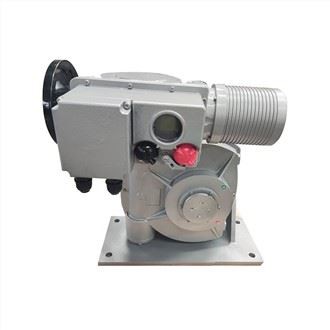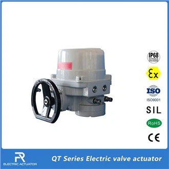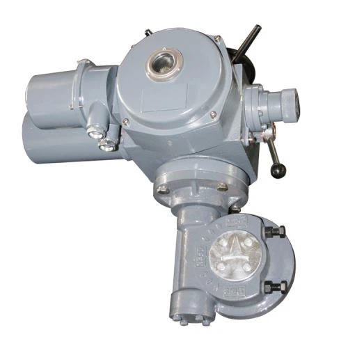


ELECTRIC VALVE ACTUATOR
PRODUCT FEATURES
• Q type electric valve actuators are suitable for butterfly valves, ball valves etc, which are required to turn 90°. These actuators are featured by small size, light weight, high efficiency, high reliability, high protection capability, low noise and so on. Both operation at site and remote controlling can be carried out. So they have been applied in petroleum and chemical industries, power plant, water treatment and paper-making industries.
• Freya controls designs, produces and provides high-quality actuators and services related to valve automation.
• With our many years of experience in the field of automation, we have launched the Q series of electric actuators, which are compact, rugged, reliable and can be fully integrated into complex control systems.
• We are always ready to provide you with our Q series actuators and accessories as well as quality services.
• Compact and robust construction, lightweight.
• Wide range of torque variation (From min 50Nm to max 5000Nm).
• Hard anodized aluminum housing inside and outside with external high temperature paint coating for use against severe industrial environment.
• Enclosure uses radial seals & O-rings that provide protection to waterproof IP67 and optional watertight lP68.
• lSO5211 standard.
• Removable drive bushing for easy machining and mounting.
• Self-locking provided by double worm gearing (no brake required).
• It automatically identifies and corrects phases. Automatic phase failure protection protects equipment safety.
•Reliable mechanical torque sensing system providing safe operation in overload condition.
• Large size window and indicator provides better position indication from a distance.
• Number of local position control options to provide easy commissioning and field operation.
PRODUCT STRUCTURE


1 Integrated control unit Non-sunk switch button is adopted to ensure complete waterproof function. The built-in circuit board has a reliable power isolation from external interference signals by optical isolation elements. If there is an over-torque switch induction, for the safety of the motor and valve, the actuator will refuse to be sensed by other sensors before the operator inputs the home position (RESET) button.
2 Selection of control mode
The selective switch "Remote"-"Stop"-"Local" installed on the local operating device can be used to set up remote operation (remote control) or local operation (local control) or stop mode.
3 Local electric operation
The operating switch "Open"-"Close" installed on the local operating device can be used to open or close actuator locally.
4 Motor
The valve-specific motor that can be disassembled independently has the characteristics of high starting torque and small inertia. The squirrel cage induction motor with embedded thermostat. The built-in thermostat accurately detects the increased temperature to prevent form motor damaging.
5 Electric operation
The motor drives the electric worm through a first-stage spur gear pair, and the worm drives the eccentric shaft to rotate through the copper worm gear combined with it. This reduction gear structure has self-locking performance, when the motor stops, the valve will be locked in position.
6 Stroke control, torque control and opening indicating mechanism
Stroke control It adopts a cam mechanism, the cam shaft is synchronized with the output shaft and two micro switches are respectively set in the opening and closing directions.The upper end of the cam shaft is equipped with a dial to indicate the valve position. Torque control The electric worm is equipped with a butterfly spring group, the axial movement of the electric worm is proportional to the output torque of the output shaft, and the movement of the worm is converted into the rotation of the torque shaft through the rack and pinion structure. A cam is installed on the torque shaft, and a microswitch is provided correspondingly in the direction of opening and closing.
7 Manual operation
When the handwheel is turned, the manual worm drives the outer gear of the fixed ring gear to rotate, and the inner gear of the fixed ring gear and the planetary gear form a fixed-axis gear train to drive the output shaft to rotate. Therefore the manual and electric operation conversion of the actuators is completed through the role conversion of the static ring gear. There is no clutch, and there is no need to switch the handle to achieve fully automatic switching.
8 Terminal box
The independent sealed terminal cavity can ensure the sealing integrity of the electrical part of the electric actuator when performing on-site wiring, and at the same time meet the product explosion-proof requirements.
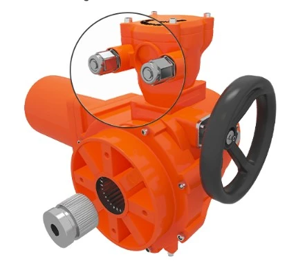
9 Mechanical limit
There is an adjustable limit screw in each direction of opening and closing. A special sealing gasket is installed on the limit screw to ensure good sealing performance of this part.
FIELD CASES


PRODUCT ACCESSORIES

EXPLOSION-PROOF TYPE ELECTRIC ACTUATOR
What is a Explosion-proof Type Electric Actuator?
Zones - Explosion groups - Temperature classes
Implementation
Areas with potentially explosive atmospheres are divided into zones, equipment has to be divided into groups and categories. The labelling on the identification plate of certified equipment indicates in which zone the explosion protected equipment can be used.
Division into product groups
Equipment is divided into group I and group II. Group I consists of underground mines and group II deals with all other applications.
Division into zones
Areas with potentially explosive atmospheres are divided into six zones according to the probability of how frequent and for which period of time a potentially explosive atmosphere (p.e.a.) exists.
A distinction is made between combustible gases, mists, vapors and combustible dust. For gases, mists and vapors zones 0, 1 and 2 exist, in which the requirements for the chosen equipment increase from zone 2 to 0. Equipment in zone 0 must be built in a way "that even if a type of protection fails or if two faults occur, that sufficient explosion protection is guaranteed". Therefore for example a passive, potential free sensor, installed in zone 0, and connected to an intrinsically safe electric circuit (II 2 (1) G [Ex ia] IIC), needs its own approval. Zones 20, 21 and 22 are for dust atmospheres, in which the requirements for the chosen equipment increase from zone 22 to 20. Equipment in zone 20 and 21 need special approval.


Example: Spray room with Ex zones, air handling system and Schischek Ex-proof components

Example: Filling station with Ex zones (Hazardous locations)

Example of a typical zone activity would be filling a barrel of petrol in an enclosed area.
Example of a typical zone activity would be filling a grain silo in an enclosed area.
Division into equipment groups
Equipment groups determine, in which zones the equipment may be installed. Once again there are six categories. Categories 1G, 2G and 3G are classifications for gas explosion protection (G = Gas); thereby 1G equipment is suitable for use in zones 0, 1 and 2, 2G equipment is suitable for use in zones 1 and 2 and 3G equipment is suitable for use in zone 2. Categories 1D, 2D and 3D are classifications for dust explosion protection (D = Dust); thereby 1D equipment is suitable for use in zones 20, 21 and 22, 2D equipment is suitable for use in zones 21 and 22 and 3D equipment is suitable for use in zone 2.
Division into explosion groups
Explosion protected equipment for gases, mists and vapors is divided into three explosion groups (IIA-IIB-IIC) according to the type of protection being used. The explosion group is a means to measure the ignitability of gases (potentially explosive atmos- pheres). The equipment requirements increase from IIA to IIC.
Division into temperature classes
Explosion proof equipment, installed within an Ex area, is divided into 6 temperature classes (T1 to T6). The temperature class is not – as it is often wrongly believed – the operating temperature range of the equipment, but the maximum permissible surface temperature of the equipment, in relation to + 40°C ambient temperature on any surface area, which may not be exceeded at any time. The maximum surface temperature must remain below the ignition temperature of the surroun-ding medium at all times. The equip-ment design requirements increase from T1 to T6.


How to Achieve Explosion-proof?
The explosion-proof electric actuator must be produced in accordance with the ISO 9001 quality system standard. The explosion-proof function is designed and produced in accordance with the national electrical explosion-proof standards GB3836.2 (gas explosion-proof) and GB12476 (dust explosion-proof) and has passed explosion-proof certification. Domestic must obtain: "China National Compulsory Product Certification", "Explosion-proof Certificate", and foreign export also need to obtain relevant explosion-proof certification: "IECEX", "ATEX", "Customs Union CU-TR Explosion-proof Certification".
This type of explosion-proof electric actuator can withstand the internal explosion of a flammable mixture that has entered the interior of the housing without damage, and will not ignite through any joints or holes in the housing by one or more gases or vapors
The enclosure of electrical equipment that forms an external explosive atmosphere.
The explosion-proof level of FRY explosion-proof series electric actuator is: ExdⅡBT4Gb Ex - Explosion proof identification
D - Explosion Proof or Explosion Proof - Equipment type represents electrical equipment designed for explosive gas atmospheres other than coal mines
B - the size of the explosion, which determines the dimensions (width and clearance) of each fire joint of the actuator;
T4 - Temperature class represents the maximum allowable surface temperature of the actuator of 135°C Gb - Protection class standard
Hazards of Counterfeit Explosion-proof Products
Nowadays, there are many fine smartelectric actuators pseudo-explosion-proof/ explosion-proof products on the market, which are extremely harmful. Sparks, arcs or dangerous temperatures are generated in places containing flammable and explosive gases and dust such as coal, petroleum and chemical industry. , the flame of the explosion inside the equipment will be transmitted to the outside of the shell, and it will directly contact with the external flammable and explosive gas mixture, which will cause fire and gas or coal dust explosion and cause major vicious accidents. Therefore, this article teaches you how to distinguish the true and false explosion-proof electric actuators.

Explosion-proof type Electric Actuator
The explosion-proof grade of FRY series fine and small explosion-proof electric actuators produced by our company is: Exd IIC T5Gb; Note: It can be used in environments where Exd IIC T4Gb, Exd IIB T5Gb and Exd IIB T4Gb are lower than Exd IIC T5Gb.

STANDARD SPECIFICATIONS
|
Protection grade |
Standard IP65/IP67 Special IP68 |
|
Power supply |
Three-phase AC380V---460V 50/60Hz Single-phase: AC110V-AC220V DC24V AC24V 50/60Hz |
|
Duty cycle(on-off) |
Short 10 minutes (special order 30 minutes) |
|
Duty cycle(modulating) |
Short 10 minutes (special order 30 minutes) |
|
Motor |
Squirrel cage induction motor |
|
Limit switches |
2 each for open and close (SPDT 250VAC/16A rating) |
|
Torque switches |
1 each for open and close (SPDT 250VAC/16A rating) |
|
Jam protection |
Build-in overheat protection |
|
Travel angle |
90° |
|
Position indicator |
Continuous mechanical indicator with arrow |
|
Self locking |
Provided by double worm gearing (no brake) |
|
Mechanical stopper |
1 each for each travel end (open and close), external & adjustable |
|
Ambient temperature |
Standard: -20~+60℃ Optional: -40~+80℃ |
|
Ambient humidity |
90%RH max (Non-condensing) |
|
Explosion-proof grade |
ExdIIBT4 IECEx ATEx customized certification can be provided |
|
Functions |
LCD Chinese / English display window and local operation function Self phase sequence identifying and phase disconnection protection Infrared setting and control Fault self-diagnosis technology Modbus, Profidbus DP, Hart |
|
Signal |
A: Remote passive dry contact, signal short pulse (Inching). B: Remote passive dry contact, signal long pulse (hold). C: Active DC24V signal. D: Active AC220V signal. E: Remote DC4-20mA signal. |
|
Feedback signal |
A: Open, close, stop signals (passive dry contact). B: Fault signal (passive dry contact). C: Valve position signal (DC4-20mA, DC1-5V, DC0-10V) D: Remote control signal (passive dry contact) |
TECHNICAL DATA
|
Model |
Torque (N·m) |
Max. stem diameter (mm) |
Manual ratio |
Output speed (r/min) |
AC380V |
AC220V |
Weight Kg |
|||
|
Power (KW) |
Current (A) |
Power (KW) |
Current (A) |
Direct mounted |
Foot-plate mounted |
|||||
|
FRY-Q-005 |
50 |
19 |
60:1 |
0.5 |
0.045 |
0.35 |
0.06 |
0.7 |
8.5 |
16 |
|
FRY-Q-010 |
100 |
19 |
60:1 |
0.5 |
0.06 |
0.5 |
0.09 |
1.0 |
9 |
17 |
|
FRY-Q-015 |
100 |
28 |
90:1 |
0.5 |
0.06 |
0.5 |
0.09 |
1.0 |
17 |
25 |
|
FRY-Q-020 |
200 |
28 |
90:1 |
0.5 |
0.09 |
0.7 |
0.12 |
1.5 |
17 |
25 |
|
FRY-Q-030 |
300 |
28 |
90:1 |
0.5 |
0.12 |
0.8 |
0.15 |
2.0 |
17 |
25 |
|
FRY-Q-040 |
400 |
28 |
90:1 |
0.5 |
0.15 |
0.9 |
0.18 |
2.5 |
18 |
26 |
|
FRY-Q-060 |
600 |
38 |
87:1 |
0.5 |
0.18 |
1.0 |
0.25 |
3.0 |
25 |
41 |
|
FRY-Q-090 |
900 |
38 |
87:1 |
0.5 |
0.25 |
1.5 |
0.37 |
4.0 |
26 |
50 |
|
FRY-Q-120 |
1200 |
38 |
87:1 |
0.5 |
0.25 |
1.5 |
0.37 |
4.0 |
27 |
51 |
|
FRY-Q-180 |
1800 |
38 |
87:1 |
0.5 |
0.37 |
2.0 |
0.55 |
5.0 |
28 |
67 |
|
FRY-Q-300 |
3000 |
55 |
348:1 |
0.5 |
0.37 |
2.0 |
0.55 |
5.0 |
39 |
77 |
|
FRY-Q-400 |
4000 |
55 |
348:1 |
0.5 |
0.55 |
3.0 |
0.75 |
7.0 |
40 |
78 |
|
FRY-Q-500 |
5000 |
55 |
348:1 |
0.5 |
0.55 |
3.0 |
0.75 |
7.0 |
41 |
82 |
Note:
1. Under the rated voltage, the ratio of the jam current to the rated current of the motor is 7, and the tolerance is +20% of the guaranteed value
2. lf there are special requirements, the company can provide other speeds: 0.25/1/2/3/4 (r/min), etc.
DIMENSIONS

|
Model |
B1 |
B2 |
H |
H1 |
H2 |
L |
L1 |
D |
|
FRY-Q-005/015 |
68 |
114 |
156 |
270 |
73 |
250 |
157 |
140 |
|
FRY-Q-020/040 |
91 |
157 |
191 |
273 |
103 |
332 |
208 |
160 |
|
FRY-Q-060/180 |
143 |
203 |
227 |
309 |
126 |
424 |
232 |
250 |
|
FRY-Q-300/800 |
143 |
203 |
291 |
373 |
190 |
424 |
232 |
250 |
CONNECTION DIMENSIONS

|
Model |
B1 |
B2 |
H |
H1 |
H2 |
L |
L1 |
D |
|
FRY-Q-005/015 |
68 |
114 |
156 |
270 |
73 |
250 |
157 |
140 |
|
FRY-Q-020/040 |
91 |
157 |
191 |
273 |
103 |
332 |
208 |
160 |
|
FRY-Q-060/180 |
143 |
203 |
227 |
309 |
126 |
424 |
232 |
250 |
|
FRY-Q-300/800 |
143 |
203 |
291 |
373 |
190 |
424 |
232 |
250 |
CONNECTION DIMENSIONS

|
Model |
Flange model |
d1 |
d2 |
d3 |
n-d4 |
D7 |
H |
h |
h1 |
||
|
Reserved |
Max. |
||||||||||
|
FRY-Q-005 |
FB1 |
77 |
57 |
4-M6 |
12.7 |
12.7 |
35 |
||||
|
FRY-Q-010 |
FB1 |
77 |
57 |
4-M6 |
15.9 |
15.9 |
35 |
3 |
2 |
||
|
F05 |
65 |
35 |
50 |
4-M6 |
8 |
18 |
35 |
||||
|
FRY-Q-015 FRY-Q-020 |
FB2 |
92 |
70 |
4-M8 |
19 |
19 |
42 |
||||
|
F07 |
90 |
55 |
70 |
4-M8 |
12 |
28 |
42 |
3 |
2 |
||
|
FRY-Q-030 FRY-Q-040 |
FB3 |
115 |
89 |
4-M12 |
22.2 |
22.2 |
42 |
||||
|
F10 |
125 |
70 |
102 |
4-M10 |
12 |
28 |
42 |
3 |
2 |
||
|
FRY-Q-060 |
FB3 |
115 |
89 |
4-M12 |
28.6 |
28.6 |
50 |
||||
|
F10 |
125 |
70 |
102 |
4-M10 |
15 |
38 |
50 |
3 |
2 |
||
|
FRY-Q-120 |
FB4 |
140 |
108 |
4-M12 |
31.7 |
31.7 |
50 |
||||
|
F12 |
150 |
85 |
125 |
4-M12 |
15 |
38 |
50 |
3 |
2 |
||
|
FRY-Q-120 FRY-Q-180 |
FB5 |
197 |
159 |
4-M16 |
33.3 |
33.3 |
60 |
||||
|
F14 |
175 |
100 |
140 |
4-M16 |
20 |
38 |
60 |
3 |
3 |
||
|
FRY-Q-180 FRY-Q-300 FRY-Q-500 |
FB5 |
197 |
159 |
4-M16 |
41.3 |
41.3 |
90 |
||||
|
F16 |
210 |
130 |
165 |
4-M20 |
20 |
60 |
90 |
3 |
3 |
||
FACTORY

Hot Tags: Explosion-proof Type Electric Valve Actuator, China, manufacturers, suppliers, factory, buy, price, quotation, Quarter Turn Electric Actuator, Motor Operated Butterfly Valve, Linear Electric Actuator For Rotork, Electric Gate Valve, Part turn Butterfly Valve Actuator, 220v Butterfly Valve Electric Actuator