ELECTRIC VALVE ACTUATOR

PRODUCT FEATURES
• Q type electric valve actuators are suitable for butterfly valves, ball valves etc, which are required to turn 90°. These actuators are featured by small size, light weight, high efficiency, high reliability, high protection capability, low noise and so on. Both operation at site and remote controlling can be carried out. So they have been applied in petroleum and chemical industries, power plant, water treatment and paper-making industries.
• Freya controls designs, produces and provides high-quality actuators and services related to valve automation.
• With our many years of experience in the field of automation, we have launched the Q series of electric actuators, which are compact, rugged, reliable and can be fully integrated into complex control systems.
• We are always ready to provide you with our Q series actuators and accessories as well as quality services.
• Compact and robust construction, lightweight.
• Wide range of torque variation (From min 50Nm to max 5000Nm).
• Hard anodized aluminum housing inside and outside with external high temperature paint coating for use against severe industrial environment.
• Enclosure uses radial seals & O-rings that provide protection to waterproof IP67 and optional watertight lP68.
• lSO5211 standard.
• Removable drive bushing for easy machining and mounting.
• Self-locking provided by double worm gearing (no brake required).
• It automatically identifies and corrects phases. Automatic phase failure protection protects equipment safety.
•Reliable mechanical torque sensing system providing safe operation in overload condition.
• Large size window and indicator provides better position indication from a distance.
• Number of local position control options to provide easy commissioning and field operation.
PRODUCT STRUCTURE


1 Integrated control unit Non-sunk switch button is adopted to ensure complete waterproof function. The built-in circuit board has a reliable power isolation from external interference signals by optical isolation elements. If there is an over-torque switch induction, for the safety of the motor and valve, the actuator will refuse to be sensed by other sensors before the operator inputs the home position (RESET) button.
2 Selection of control mode
The selective switch "Remote"-"Stop"-"Local" installed on the local operating device can be used to set up remote operation (remote control) or local operation (local control) or stop mode.
3 Local electric operation
The operating switch "Open"-"Close" installed on the local operating device can be used to open or close actuator locally.
4 Motor
The valve-specific motor that can be disassembled independently has the characteristics of high starting torque and small inertia. The squirrel cage induction motor with embedded thermostat. The built-in thermostat accurately detects the increased temperature to prevent form motor damaging.
5 Electric operation
The motor drives the electric worm through a first-stage spur gear pair, and the worm drives the eccentric shaft to rotate through the copper worm gear combined with it. This reduction gear structure has self-locking performance, when the motor stops, the valve will be locked in position.
6 Stroke control, torque control and opening indicating mechanism
Stroke control It adopts a cam mechanism, the cam shaft is synchronized with the output shaft and two micro switches are respectively set in the opening and closing directions.The upper end of the cam shaft is equipped with a dial to indicate the valve position. Torque control The electric worm is equipped with a butterfly spring group, the axial movement of the electric worm is proportional to the output torque of the output shaft, and the movement of the worm is converted into the rotation of the torque shaft through the rack and pinion structure. A cam is installed on the torque shaft, and a microswitch is provided correspondingly in the direction of opening and closing.
7 Manual operation
When the handwheel is turned, the manual worm drives the outer gear of the fixed ring gear to rotate, and the inner gear of the fixed ring gear and the planetary gear form a fixed-axis gear train to drive the output shaft to rotate. Therefore the manual and electric operation conversion of the actuators is completed through the role conversion of the static ring gear. There is no clutch, and there is no need to switch the handle to achieve fully automatic switching.
8 Terminal box
The independent sealed terminal cavity can ensure the sealing integrity of the electrical part of the electric actuator when performing on-site wiring, and at the same time meet the product explosion-proof requirements.
9 Mechanical limit
There is an adjustable limit screw in each direction of opening and closing. A special sealing gasket is installed on the limit screw to ensure good sealing performance of this part.
FIELD CASES


PRODUCT ACCESSORIES

PROTECTION GRADE CAN BE CUSTOMIZED
What is the Electric Actuator Protection Grade?
IP (INGRESS Protection) protection grade system is drafted by IEC (International Electrotechnical Commission) and classifies the electrical appliances according to the characteristics of its dustproof and humidity. The IP protection grade is composed of two numbers. The first number represents the grade of electrical dustproof and the grade of preventing foreign objects from invading (the foreign objects referred to here contain tools, and human fingers cannot be exposed to the inside of the electrical appliances. In order to avoid electric shock), the second number indicates the degree of conflict of moisture and waterproofing in electrical appliances. The larger the number, the higher the protection grade.
The protection grade is one of the important parameters of the valve electric actuator. Different protection grades and prices are different. Generally speaking, the protection grade is represented by IP00, and the two numbers behind IP represent the size of the protection grade. So what does these numbers mean? What are the different protection grades different?
First, the first number indicates the level of contact protection and the protection grade of foreign objects (protection scope)
0 - No protection. 1 -Protective 50mm diameter and larger solid external body.
2 -Protective 12.5mm diameter and larger solid exterior.
3 - Protecting 2.5mm diameter and larger solid external body.
4 -Protective 1.0mm diameter and larger solid exterior.
5 - Protective dust cannot be completely prevented from entering the dust, but the number of dust entry will not cause damage to the equipment.
6 - The closed dust is completely prevented from invading foreign objects and can completely prevent dust from entering. The second number represents waterproof protection level (protection scope)
0 - No protection.
1 - water droplets falling vertically, water droplets should not cause damage.
2 -When the water drop cabinet is tilted to any side of the 15 degrees, the droplets falling vertically should not cause damage.
3 -The water sprayed from the 60 -degree angle of the vertical line of the protection sprayed should not cause damage.
4 -Water that splashed water splashed from every direction should not cause damage.
5 -The water that protects the sprayed water from each direction to the water ejected by the nozzle of the cabinet should not cause damage.
6 - Protective strong radiation water should not cause damage to the strong ejection water from each direction.
7 - When the protection of water is immersed in the water for short -term immersion in the water for a short time, ensure that it is not damaged due to water.
8 - Long -term protection of protection can be immersed in water under specific conditions to ensure that it is not damaged due to water.

IP Test
⑴IPX 1
Method name: Vertical drip test Test equipment: dripping test device Sample placement: Place the position of a 1R/min rotating sample table according to the normal working position of the sample.
Test condition: dripping amount is 1.0 ± 0.5mm/min Duration: 10 min
⑵IPX 2
Method Name: Liggle 15 ° Drip Water Test Test equipment: dripping test device
Sample placement: The distance from the top of the sample to the vertical line is 15 °, and the distance from the top of the sample to the drip exit is not more than 200mm. After each test, change the other side for four times.
Test condition: dripping amount is 3.0 ± 0.5 mm/min Duration: 4 × 2.5 min (total 10 min)
(3)Ipx 3
Method Name: Dripping Water Test experiment method: a. Tube -type leaching test
Test equipment: Tube pipe splashing water test device
Sample placement: Select the tube of the appropriate radius, so that the sample countertop is at the height of the pipe tube diameter.
Place the sample on the sample platform so that the distance from the top to the sample water outlet is not more than 200mm, and the sample table will not rotate.
Test conditions: The water flow is calculated according to the number of water spray holes in the tube, and each hole is 0.07 L/min.
When the water is poured, the water spray pores in the 60 ° arc segments on both sides of the pipe are sprayed towards the sample.
The sample sample is placed in the pipe semicircle center.
The pipes are swinged on both sides of the vertical line for 60 °, a total of 120 °. Each swing (2 × 120 °) is about 4S
Test time: continuous water 10 min 10 min
b. Spirit -style leaching test Test equipment: Handheld water splash water test device
Sample placement: The parallel distance from the top of the test to the handheld nozzle water port is between 300mm and 500mm
Test conditions: In the test, the baffle with a balanced heavy object should be installed, and the water flow is 10 L/min
Test time: calculate according to the area of the sample shell surface, 1 min per square meter (excluding the installation area), at least 5 min 5 min
⑷IPX 4
Method name: Splash Test experiment method: a.Test equipment and sample placement: the same as the A number of the above IPX 3;
Test conditions: Except for the following conditions, the same as the A number of the above IPX 3 is the same;
the water spray area is the spray spray spray of water spray pores in the 90 ° arc section of the pipe in the middle point.
The sample sample is placed in the pipe semicircle center.
The pipe pipe is 180 ° on the two sides of the vertical line, about 360 °.
Show each time (2 × 360 °) about 12S Test time: the same as the A number of the above IPX 3 (that is, 10 min).
b. Torch splash test Test device and sample placement: the same as the B of the above IPX 3;
Test conditions: Disassemble the device with a baffle with a balanced heavy object, the rest are the same as the B of the above IPX 3;
Test time: the same as the B of the above IPX 3, that is, calculated according to the area of the sample shell surface, 1 min per square meter (excluding the installation area) at least 5 minutes per square meter
⑸IPX 5
Method name: water spray test Test equipment: The inner diameter of the nozzle of the nozzle is 6.3mm
Test conditions: Make the test sample from 2.5m ~ 3m apart, and the water flow is 12.5 L/min (750 L/h)
Test time: Calculated according to the area of the sample shell surface, 1 min per square meter (excluding the installation area) at least 3 minutes
⑹IPX 6
Method name: strong water spray test;
Test equipment: The inner diameter of the nozzle of the nozzle is 12.5 mm
Test conditions: Make the test sample from 2.5m ~ 3m apart, and the water flow is 100 L/min (6000 L/h)
Test time: Calculated according to the area of the sample shell surface, 1 min per square meter (excluding the installation area) at least 3 minutes
⑺IPX 7
Method name: short -term water dipping test Test equipment and test conditions: dipping water tank.
The size of the sample should be placed in the water tank, and the distance from the bottom of the sample to the water surface is at least 1m.
The distance from the top of the sample to the water surface is at least 0.15m Test time: 30 min
⑻IPX 8
Method name: Continuous diving test; Test equipment, test conditions and test time: agreed by both supply and demand (buying and selling), and its strict degree should be higher than the IPX 7.
Note: In addition, many outdoor electronic products are also emphasizing floating capabilities.

Know the Waterproof Level of Electronic Products JIS (ipx)
0 non -protection
1 Anti -drop I -type water droplets without harmful effects
2 Anti -Drop Type II and vertical directions into 15 "Drops falling in the range have no harmful effects
3 rainproof type and vertical direction into 60 degrees rainfall has no harmful effects
4 Splash -proof type of water splashing in any direction has no harmful effect
5 Anti -spray type any direction is directly affected by water injection without harmful effects
6 The spraying of water to any direction of water -resistant type will not enter the interior without spraying water
7 The anti -immersion type will not enter the interior even if it is immersed in the water
8 The water in the water can be used for a long time in water that is not soaked in a certain pressure.
9 Wet -proof type can still be used when the relative humidity is more than 90%of moisture
The IP waterproof grade of international industrial standards and the JIS waterproof level of Japanese industrial standards are close. It is divided into 9 levels of 0-8. The IP level also provides dustproof.
IPXX dustproof waterproof level Dust -proof grade (first x indicated)
0: No protection
1: Prevent large solid intrusion
2: Prevent medium -sized solid intrusion
3: Prevent small solids from entering invasion
4: Prevent objects from objects greater than 1mm
5: Prevent harmful dust accumulation 6: completely prevent dust from entering Waterproof level (second x indicated)
0: No protection 1: Drops of water into the shell have no effect
2: When the shell is tilted to 15 degrees, the water droplets have no effect on the shell
3: Water or rainwater from 60 degrees to the shell has no effect
4: The liquid is splashed from any direction to the shell without any damage effect
5: Rinse with water without any damage
6: Can be used in the environment in the cabin
7: It can be soaked in water in a short time (1M)
8: Soak water for a long time under a certain pressure Example: The scale or display instrument is marked as IP65, indicating that the product can completely prevent dust from entering and washed with water without any damage. Regulations on waterproof experiments in IPXX levels.


Protection Grade Certificate
Industrial automation is the foundation of industrial modernization, and plays an important role in traditional industrial reform and the adjustment and optimization of industrial structure. With the development of computer network communication technology and electronic electronic technology, the industrial automation control system is constantly optimizing and updating. In the face of increasingly complex production processes and environments, the requirements for valve controllers are also increasing to meet the requirements of modern automation production.
In this case, it is necessary to correctly grasp the quality of the product, do a good job of protection testing, and ensure the quality of the control valve.

IP68 is the highest level of waterproof level standards. Everyone knows how the waterproof performance of the controller depends mainly on the latter two digits XX of the IPXX. The first x is from 0 to 6, and the highest level is 6; the second place X is from 0 to 8, the highest level is 8 is 8, the highest level is 8 is 8, the highest level is 8 is 8, and the highest level is 8. ; Therefore, the highest waterproof level of the controller is IP68. In other words, IP68 controller is the highest standard controller of waterproof level, and IP68 is undoubtedly a good benchmark for the improvement of product quality.
STANDARD SPECIFICATIONS
|
Protection grade |
Standard IP65/IP67 Special IP68 |
|
Power supply |
Three-phase AC380V---460V 50/60Hz Single-phase: AC110V-AC220V DC24V AC24V 50/60Hz |
|
Duty cycle(on-off) |
Short 10 minutes (special order 30 minutes) |
|
Duty cycle(modulating) |
Short 10 minutes (special order 30 minutes) |
|
Motor |
Squirrel cage induction motor |
|
Limit switches |
2 each for open and close (SPDT 250VAC/16A rating) |
|
Torque switches |
1 each for open and close (SPDT 250VAC/16A rating) |
|
Jam protection |
Build-in overheat protection |
|
Travel angle |
90° |
|
Position indicator |
Continuous mechanical indicator with arrow |
|
Self locking |
Provided by double worm gearing (no brake) |
|
Mechanical stopper |
1 each for each travel end (open and close), external & adjustable |
|
Ambient temperature |
Standard: -20~+60℃ Optional: -40~+80℃ |
|
Ambient humidity |
90%RH max (Non-condensing) |
|
Explosion-proof grade |
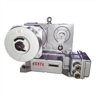
ExdIIBT4 IECEx ATEx customized certification can be provided |
|
Functions |
LCD Chinese / English display window and local operation function Self phase sequence identifying and phase disconnection protection Infrared setting and control Fault self-diagnosis technology Modbus, Profidbus DP, Hart |
|
Signal |
A: Remote passive dry contact, signal short pulse (Inching). B: Remote passive dry contact, signal long pulse (hold). C: Active DC24V signal. D: Active AC220V signal. E: Remote DC4-20mA signal. |
|
Feedback signal |
A: Open, close, stop signals (passive dry contact). B: Fault signal (passive dry contact). C: Valve position signal (DC4-20mA, DC1-5V, DC0-10V) D: Remote control signal (passive dry contact) |
TECHNICAL DATA
|
Model |
Torque (N·m) |
Max. stem diameter (mm) |
Manual ratio |
Output speed (r/min) |
AC380V |
AC220V |
Weight Kg |
|||
|
Power (KW) |
Current (A) |
Power (KW) |
Current (A) |
Direct mounted |
Foot-plate mounted |
|||||
|
FRY-Q-005 |
50 |
19 |
60:1 |
0.5 |
0.045 |
0.35 |
0.06 |
0.7 |
8.5 |
16 |
|
FRY-Q-010 |
100 |
19 |
60:1 |
0.5 |
0.06 |
0.5 |
0.09 |
1.0 |
9 |
17 |
|
FRY-Q-015 |
100 |
28 |
90:1 |
0.5 |
0.06 |
0.5 |
0.09 |
1.0 |
17 |
25 |
|
FRY-Q-020 |
200 |
28 |
90:1 |
0.5 |
0.09 |
0.7 |
0.12 |
1.5 |
17 |
25 |
|
FRY-Q-030 |
300 |
28 |
90:1 |
0.5 |
0.12 |
0.8 |
0.15 |
2.0 |
17 |
25 |
|
FRY-Q-040 |
400 |
28 |
90:1 |
0.5 |
0.15 |
0.9 |
0.18 |
2.5 |
18 |
26 |
|
FRY-Q-060 |
600 |
38 |
87:1 |
0.5 |
0.18 |
1.0 |
0.25 |
3.0 |
25 |
41 |
|
FRY-Q-090 |
900 |
38 |
87:1 |
0.5 |
0.25 |
1.5 |
0.37 |
4.0 |
26 |
50 |
|
FRY-Q-120 |
1200 |
38 |
87:1 |
0.5 |
0.25 |
1.5 |
0.37 |
4.0 |
27 |
51 |
|
FRY-Q-180 |
1800 |
38 |
87:1 |
0.5 |
0.37 |
2.0 |
0.55 |
5.0 |
28 |
67 |
|
FRY-Q-300 |
3000 |
55 |
348:1 |
0.5 |
0.37 |
2.0 |
0.55 |
5.0 |
39 |
77 |
|
FRY-Q-400 |
4000 |
55 |
348:1 |
0.5 |
0.55 |
3.0 |
0.75 |
7.0 |
40 |
78 |
|
FRY-Q-500 |
5000 |
55 |
348:1 |
0.5 |
0.55 |
3.0 |
0.75 |
7.0 |
41 |
82 |
Note:
1. Under the rated voltage, the ratio of the jam current to the rated current of the motor is 7, and the tolerance is +20% of the guaranteed value
2. lf there are special requirements, the company can provide other speeds: 0.25/1/2/3/4 (r/min), etc.
DIMENSIONS

|
Model |
B1 |
B2 |
H |
H1 |
H2 |
L |
L1 |
D |
|
FRY-Q-005/015 |
68 |
114 |
156 |
270 |
73 |
250 |
157 |
140 |
|
FRY-Q-020/040 |
91 |
157 |
191 |
273 |
103 |
332 |
208 |
160 |
|
FRY-Q-060/180 |
143 |
203 |
227 |
309 |
126 |
424 |
232 |
250 |
|
FRY-Q-300/800 |
143 |
203 |
291 |
373 |
190 |
424 |
232 |
250 |
CONNECTION DIMENSIONS

|
Model |
Flange model |
d1 |
d2 |
d3 |
n-d4 |
D7 |
H |
h |
h1 |
||
|
Reserved |
Max. |
||||||||||
|
FRY-Q-005 |
FB1 |
77 |
57 |
4-M6 |
12.7 |
12.7 |
35 |
||||
|
FRY-Q-010 |
FB1 |
77 |
57 |
4-M6 |
15.9 |
15.9 |
35 |
3 |
2 |
||
|
F05 |
65 |
35 |
50 |
4-M6 |
8 |
18 |
35 |
||||
|
FRY-Q-015 FRY-Q-020 |
FB2 |
92 |
70 |
4-M8 |
19 |
19 |
42 |
||||
|
F07 |
90 |
55 |
70 |
4-M8 |
12 |
28 |
42 |
3 |
2 |
||
|
FRY-Q-030 FRY-Q-040 |
FB3 |
115 |
89 |
4-M12 |
22.2 |
22.2 |
42 |
||||
|
F10 |
125 |
70 |
102 |
4-M10 |
12 |
28 |
42 |
3 |
2 |
||
|
FRY-Q-060 |
FB3 |
115 |
89 |
4-M12 |
28.6 |
28.6 |
50 |
||||
|
F10 |
125 |
70 |
102 |
4-M10 |
15 |
38 |
50 |
3 |
2 |
||
|
FRY-Q-120 |
FB4 |
140 |
108 |
4-M12 |
31.7 |
31.7 |
50 |
||||
|
F12 |
150 |
85 |
125 |
4-M12 |
15 |
38 |
50 |
3 |
2 |
||
|
FRY-Q-120 FRY-Q-180 |
FB5 |
197 |
159 |
4-M16 |
33.3 |
33.3 |
60 |
||||
|
F14 |
175 |
100 |
140 |
4-M16 |
20 |
38 |
60 |
3 |
3 |
||
|
FRY-Q-180 FRY-Q-300 FRY-Q-500 |
FB5 |
197 |
159 |
4-M16 |
41.3 |
41.3 |
90 |
||||
|
F16 |
210 |
130 |
165 |
4-M20 |
20 |
60 |
90 |
3 |
3 |
||
FACTORY

Hot Tags: Protection Grade Custom Electric Valve Actuator, China, manufacturers, suppliers, factory, buy, price, quotation, Electric Gate Valve, Modulating Valve Actuator, Explosion Proof Electric Actuator, Quarter Turn Electric Actuator, Part turn Butterfly Valve Actuator, Angular Travel For Rotork Actuator