



Electric Actuator
The multi-turn electric actuator is the most basic actuator, which provides multi-turn (over 360° rotation) operation output drive, and is mainly used with various gate valves, globe valves, etc. The main technical parameters for the selection of multi-turn electric actuators are: closing torque (Nm) and output shaft speed (rpm). The mechanical interface (output shaft and flange) of the multi-turn actuator conforms to the national standard GB/T12222 and the international standard ISO 5210, and can realize reasonable mechanical connection with different controlled objects. The special flange connection method can also be customized according to the user.

Design Features – Protective
Graphical interface, remote indication and data logger are accessible without power
Explosion-proof according to international standards
Oil bath lubrication for long life and ability to mount in any orientation
Enhanced protection through the use of independent torque and position sensing
Double sealed for 10 days to IP66/68 20 meters
Safe, motor-independent handwheel operation
Detailed trend analysis and diagnostic data available for asset management
Bluetooth setup tool allows for secure control and indication configuration in the field
A range of high output speed actuators with integral planetary gears are available. The transmission is optimized, irreversible and provides self-locking function for the valve.
The actuator was developed specifically for diverter valves in flow meter applications that require fast operation with positive sealing and zero backdrive.
Easy installation and maintenance with removable thrust base
Always-on position sensing, even without power
Compatible with various fieldbus, hardwired and analog site systems
Design Features – Protection
Protection is key
Rich experience in the use of electric actuators makes the product a leader in actuator protection. Actuators operate reliably in humid, extremely cold or hot air environments, strong UV rays and corrosives from deserts, tundra, sea level to underground. The most important factor in terms of actuator reliability is the protection from the environment, in short, the protective housing. Default phase protection The electronics of the electric actuator monitors all three phases of the power supply to prevent the motor from overheating. If one or more phases are lost, the controller will prevent excitation through the control circuit. The actuator also displays default phasing information for the power supply and can provide remote indication of alarm status.
Motor protection when the valve is blocked
If the valve is stuck and does not move within 5 seconds after the start signal is sent, the logic circuit will disconnect the responding contactor, and at the same time send out a fault message alarm to prevent the motor from overheating.
Overheating protection
There are two thermal protection relays inside the electrical coil. If the coil is overheated, the temperature regulator in the motor coil can directly detect the temperature of the coil and disconnect the control circuit of the actuator. Instant reverse protection When the actuator receives an immediate switching command, an automatic time delay circuit is used to prevent unnecessary wear of the valve stem and gearbox from shock loads. This circuit also limits inrush current through the contactor.
Double seal, double protection
Protection level IP-underwater 3 meters, 48 hours, fully waterproof and dustproof. A double sealing system ensures that internal components are protected as the watertight terminal block isolates the internal cables from the junction box. Protection is maintained even when the terminal cover is removed for field wiring, and the terminal module cover is sealed.
Non-intrusive permanent seal
When debugging the actuator on site, there is no need to remove the end cover of the electric box. All setup and adjustments are made using the provided infrared setup tool. When assembled in a controlled environment, air convection is completely eliminated and all internal components are permanently protected. Non-intrusive control means not using a thru-shaft through the control box.

Torque measurement
The actuator can reliably and accurately measure the force of operating the valve, which is the basis for the protection of the valve and the actuator. The actuators use technology that has been tested in experiments and proven in industrial practice. Accurate and repeatable torque measurements can be obtained as long as the frequency, voltage, and temperature are varied within the allowable range.
Valve position measurement
Reliable process control depends on accurate positioning of valve ends of travel. The patented non-contact position measurement system is the simplest design in actuator control. A resolver with only one moving part converts the rotation of the output center sleeve into an electrical signal, which is then compared to limits stored in secure and non-volatile memory.

Design Features – Protection
Protection is key
Rich experience in the use of electric actuators makes the product a leader in actuator protection. Actuators operate reliably in humid, extremely cold or hot air environments, strong UV rays and corrosives from deserts, tundra, sea level to underground. The most important factor in terms of actuator reliability is the protection from the environment, in short, the protective housing.
Default phase protection
The electronics of the electric actuator monitors all three phases of the power supply to prevent the motor from overheating. If one or more phases are lost, the controller will prevent excitation through the control circuit. The actuator also displays default phasing information for the power supply and can provide remote indication of alarm status.
Mechanical durability, long service life

High quality and selected materials include aluminum/low copper aluminum housing, cast iron thrust base and cast iron reduction gears (appropriate with bronze worm gears for increased gear life and efficiency).

Simplified internal gear transmission system achieves single-stage reduction from motor to output shaft; extremely reliable, efficient and easy to maintain.

Oil bath lubrication maximizes the life of mechanical components. The oil bath does not need to be replaced or serviced throughout the life of the actuator.
Electrical System Design Considering Reliability
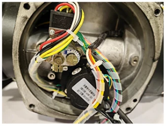
Simple yet robust absolute position encoder sensors offer high reliability and accuracy, enabling position detection even in the event of loss of main and backup power. Position accuracy is within 0.1% of true position and can record the position of the actuator output shaft for up to 8,580 complete revolutions.

High performance and reliability with solid-state control. On the local interface, the buttons are solid and offer an optional protective silicon cover to prevent the build-up of harmful particles over time.
Tested and certified for harsh environmental conditions

Wide operating temperature rating from -60°C (-76°F) to +85°C (+185°F). Hydrogen corrosion resistant material protection and certification available.

Standard integrated heater to prevent damage to the circuit board caused by low temperature

The safety system is available at Safety Integrity Level SIL 2 (one actuator) or SIL3 (two actuators, one of which is used as an alternative).
Output speed customization
Factors Affecting
Electric Actuator Torque: - Shape, coefficient of friction between electric actuator and valve, diameter of shaft, coefficient of friction of support surface, form of lining material (seat), cutting pressure difference. -Flow rate, system pressure characteristics and piping method
Combinations of electric actuators and these factors create the following torque types: Valve sealing and cracking torque, TS Frictional moment of the bearing surface, TB Dynamic Torque of Fluid Flow, TD
Static torque, Th
Torque is a function of many factors, including the actual size ratio of each manufacturer's valve parts as a measure of the general deviation in the valve torque they produce.

Selection of output speed: When selecting an electric actuator, the output speed of the electric actuator should be selected according to the switching time of the valve, and the time required for the valve to go from fully open (or fully closed) to fully closed (fully open). The output speed V can be calculated according to the following formula. V=N/T (N - the total number of revolutions of the valve, T - the entire operating time of the valve (minutes))
Selection of output torque: Electric actuators are generally designed to meet the needs of working conditions. Tianjin actuators design and manufacture electric actuators according to the working characteristics of the valve. Each electric valve needs to be opened, operated, closed and other working conditions. A certain torque is used as the power to drive the valve, so the design of the electric actuator is a very important consideration for its output torque. Each electric actuator has its own output torque parameters, so when selecting an electric actuator, the electric actuator The output torque of the actuator must be greater than the torque actually required by the valve in order to ensure the opening and closing of the valve.
Hot Tags: speed custom 24/36/48/72rpm dzw multi-turn electric actuator, China, manufacturers, suppliers, factory, buy, price, quotation, Quarter Turn Valve Actuators, Multi Turn Electric Actuators, Electric Gate Valve Actuator, On Off Type Electric Actuator, Electric Valve Actuator, High Torque Electric Actuator


