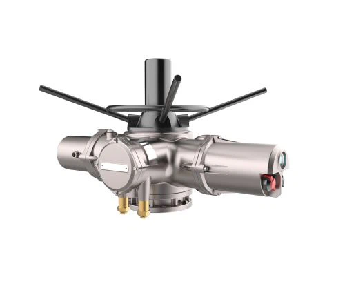
Actuator description
Quarter-turn electric actuator
Also known as part of the return receipt actuators, general rotation range of 0-90°, the output torque in Nm. Mainly used for: butterfly valve, ball valve, shutter type valve, damper, baffle and plug valve.


Linear-turn elecreic actuator
The output is indicated by N, and the output is a linear displacement.Mainly used for single, double seat control valve, sleeve valve, gate valve, etc.


Multi-turn electric actuator
Output torque in Nm, more than 360°rotation. It is mainly used for gate valve, globe valve, slide valve, high temperature and high pressure regulating valve, etc.


Main technical parameters
Input signal: 4-20mA impedance 250 Ω,0-10mA impedance 200 Ω
Dead area (sensitivity): 0.3-3% Continuous adjustable
Input channel: one analog current input channel , one set of switch volume channel .
Output channel: 4-20mA DC impedance > 50 Ω. The input channel is isolated from the output channel.
Output torque and travel.
Linear-turn: 2000N-25000N travel 10、16、25、40、100mm
Quarter-turn: 100-40000Nm travel 90°
Multi-turn: 40-400Nm travel 1-50 circle
Basic error: ±1%;±1.5%
Return difference:≦ ±1%
Damping characteristics: No oscillation (zero period oscillation)
Level of proection: IP67
Operation environment:
1. Temperature: -28--+70
2. Humidity: ≦95%
3. Shake: frequency 10-100Hz strenth, 0.5 times of acceleration of gravity
4. Impact: <5g
5. Barometric pressure: 72.5-106KPa
The non-corrosive gas media in the surrounding air must not be used in inflammable and explosive places.(The explosion-proof products can be found in my company's explosion-proof products’sample.)
voltage and power supply: 220V--±10%50Hz
Single phase: 220V--±10%50Hz
380V--±10%50Hz
Three phase: 380V--±10%50Hz
Special voltage, frequency needs to be customized in advance.
Special customized voltage

This guide is provided to assist in the sizing of actuator power supply cables, circuit protection devices and calculation of electrical diversity. The data provided is averaged from actuators of the same size, speed and voltage as recorded from production test data. As such it is not exact electrical data for individual actuators, however is sufficient for the above sizing calculations.
Test certificates for individual actuators provide unit specific loadings for the starting/stall and rated torque levels and are available when requested.
The data included is for standard duty, 3-phase supplies at the following common voltages only:
Actuators suitable for voltages other than shown above are available on request. In such cases, electrical supply sizing can be determined by using the nearest voltage published in this document.
50HZ | 60HZ |
380 | 208 |
400 | 220 |
415 | 400 |
440 | 440 |
500 | 460 |
690 | 480 |
- | 575 |
- | 600 |
To quickly access the data for your voltage, click the value in the table above. Important Notes
● Test data not available - insufficient test data available.
● Not available at this voltage - this particular build cannot be produced due to excess current draw.
Glossary
●Rated torque - the catalogued torque output of the actuator at full load. Represents a torque switch setting of 100%.
●Starting/Stall - current draw at the nominal rated voltage during the initial start of output movement or under motor stall conditions. SD standard protection prevents stall by limiting torque to approximately 150%of rated torque when torque switch bypass feature is enabled. Stall is also limited to a maximum of 5 seconds.
●Rated Torque Current - the average current draw at the nominal rated voltage when the actuator is producing the rated catalogue torque.
●Average(nominal)Torque - corresponds to approximately one third of the rated catalogued torque. This value has been confirmed after decades of valve automation and provides a representative average for load across typical valve strokes.
●Average (nominal) Current - current draw at nominal rated voltage for average nominal torque (one third rated torque).
Motor option
Extended duty cycles are available with a higher thermostat and Class H insulation for non-hazardous area applications.
Frequency Converters and UPS
Frequency converters for variable speed drives are not normally recommended as a suitable supply for SD actuators. Where UPS systems are required for back-up operation, the power supply should have negligible harmonic distortion and should output a true sine wave. In general terms actuators are designed to operate on power supplied conforming to recognised international standards such as EN 50160:2010.
Tolerances
The following tolerances may be accommodated for short term operation. It is not intended that long term operation is undertaken at supply voltage levels other than the nominal nameplate values of the supplied actuator. In general, the electrical power supply should conform to BS EN 50160:2007 (Voltage characteristics of electricity supplied by public distribution networks) or equivalent.
The volt drop developed on actuator starting must be minimised by ensuring supply capacity and cable are sufficiently sized. Starting volt drop calculation shall be based on the starting/stall currents published.
Non-standard tolerances | For tolerances larger than those quoted, contact Rotork |
Uninterruptable power supplied | For AC systems the UPS output should conform to recognised supply standards such as BS EN 50160 in respect of waveform, harmonics etc. |
Voltage Tolerance | +/-10% | Applies to rated torque performance only; duty cyde, speed and current draw is not guaranteed |
Frequency Tolerance | +/-5% | Applies to rated torque performance only; duty cyde, speed and current draw is not guaranteed |
Maximum total starting Volt Drop:IQ10-IQ35 | -15% | Actuators capable of starting |
Maximum total starting Volt Drop: IQ40-IQ95 | -10% | Actuators capable of starting |
Basic specification
Type | Torque | Voltage | Speed | Install method | Control method | Special function | code description of each part |
OA | Output torque | Working torque,digital representation,unit:Nm | |||||
AS | K | Single phase 220V.AC 50Hz | |||||
BS | F | Three phase 380V.AC 50Hz | |||||
A+RS | Power supply | Rating travel time(90°),digital representation,unit:S | |||||
B+RS | Travel time
| H | Foot-plate installation | ||||
Z | Directly mounted installation | ||||||
Ccontrol method | G | Standard integration proportional modulating,4-20mA | |||||
Y | Remote controlled, on-off input | ||||||
N | Intelligent, 4-20mA imput | ||||||
C | Main line | ||||||
Ccontrol method | P | With machine operating | |||||
Ex | Explosion-proof | ||||||
----T | Special requirements: high, low temperature, working voltage, dimension, travel, etc. |
Remark:
1.The electric actuator required by the special technology needs to write clearly and concretely in order.
2.When A+RA300/K30HGP model is A+RS, the working torque is 1000Nm, single-phase power supply, the whole travel time is 30 seconds, and foot-plate installation with integration proportional modulatin with the local operation.
Quarter-turn electrical consumption data
Type | Out put force | Torque Nm | Full Travel time | Flange equipment | Foot mounting | Motor | (Load rate 50%) | ||||
work | maximum | outside view | net weightkg | outside view | spherical hinge
| rate of work Kw | revolving speed rpm | rated current | starting current | ||
OA10K OA10F | 100 | 150 | 25 | picture | 11 | picture | SQJ-10 | 0.025 | 1500 | 1.00 | 2.00 |
0.025 | 0.35 | 1.20 | |||||||||
AS25K AS25F | 250 | 375 | 30 | 22 | SQJ-25 | 0.065 | 1500 | 1.20 | 2.60 | ||
0.065 | 0.90 | 1.80 | |||||||||
BS60K BS60F | 600 | 1000 | 30 | 32 | SQJ-60 | 0.16 | 1500 | 2.20 | 4.50 | ||
0.16 | 1.50 | 3.00 | |||||||||
A+RS100K A+RS100F | 1000 | 1400 | 30 | 48 | SQJ-100 | 0.25 | 1500 | 2.60 | 5.60 | ||
0.25 | 2.00 | 6.00 | |||||||||
B+RS160K B+RS160F | 1600 | 2000 | 40 | 76 | SQJ-160 | 0.4 | 1400 | 3.40 | 7.50 | ||
0.4 | 1.80 | 5.90 | |||||||||
B+RS250K B+RS250F | 2500 | 3000 3200 | 40 | 78 | SQJ-250 | 0.4 | 1400 | 3.40 | 7.50 | ||
0.4 | 1.80 | 5.90 | |||||||||
B+RS400K B+RS400F | 4000 | 4000 4800 | 65 | 86 | SQJ-400 | 0.4 | 1400 | 3.40 | 7.50 | ||
0.4 | 1.80 | 5.90 | |||||||||
B+RS600K B+RS600F | 6000 | 6000 6000 | 105 | 92 | SQJ-600 | 0.55 | 1400 | 3.40 | 9.60 | ||
0.4 | 2.50 | 7.50 | |||||||||
B+RS800F | 8000 | 9600 | 105 | 137 | SQJ-800 | 0.65 | 1400 | 2.50 | 9.60 | ||
B+RS1000F | 10000 | 12000 | 125 | 137 | 1.1 | 2.50 | 9.60 | ||||
B+RS1200F | 12000 | 14000 | 125 | 137 | 1.1 | 1400 | 2.80 | ||||
B+RS1400F | 14000 | 15600 | 125 | 137 | 1.1 | 1400 | 2.80 | ||||
Reliable FRY
FRY is a specialized company that has been producing electric actuators and related products that drive industrial valves since 2014 ,FRY produces product lines that can be applied in various fields,ranging from water treatment such as water supply and sewage to power generation and petrochemical fields, and sells them to customers all over the world.
FRY has a 3Q philosophy to fulfill customer needs.
Quick Delivery
FRY honors delivery dates and proposes the fastest delivery time possible.
Quick Service
FRY operates service organizations and systems to take action as quickly as possible if a problem occurs related to our product.
Quick Response
FRY works to give our customers a sense of trust by responding to customer requests as soon as they are received.
Status of major certification aquisition

Hot Tags: quarter-turn linear-turn multi-turn electric actuator voltage cusomized 220v 380v 440v 480v 550v, China, manufacturers, suppliers, factory, buy, price, quotation, Electric Actuator, Electric Rotary Valve Actuator, Explosion Proof Butterfly Valve Actuator, Angular Travel For Rotork Actuator, 220v Butterfly Valve Electric Actuator, Motor Operated Butterfly Valve