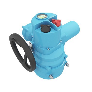
ELECTRIC VALVE ACTUATOR

PRODUCT FEATURES
● Small size and light weight. The main transmission adopts one-stage spur gear and one-stage 2K-H planetary reduction, with high strength and compact structure. Lubricating oil adopts special reducer grease.
● Equipped with stroke control mechanism, torque control mechanism, opening indicating mechanism and manual mechanism, etc., with complete functions and reliable performance.
●The manual and electric switching is fully automatic switching, without a switching handle, users do not have to worry about operating errors due to forgetting to move the handle.
● There are two cable entry ports.
● The gears are made of high-strength materials, which are heat-treated and have high strength.
● The shell of the whole machine is airtight and can be used outdoors.
● Recommend a connection size to the valve (our company's standard) to the user. In special cases, it can also be produced according to the valve size of the user.
●It is easy to install, adjust and maintain.
●The product complies with the relevant national standards.
PRODUCT STRUCTURE


1 Integrated control unit Non-sunk switch button is adopted to ensure complete waterproof function. The built-in circuit board has a reliable power isolation from external interference signals by optical isolation elements. If there is an over-torque switch induction, for the safety of the motor and valve, the actuator will refuse to be sensed by other sensors before the operator inputs the home position (RESET) button.
2 Selection of control mode
The selective switch "Remote"-"Stop"-"Local" installed on the local operating device can be used to set up remote operation (remote control) or local operation (local control) or stop mode.
3 Local electric operation
The operating switch "Open"-"Close" installed on the local operating device can be used to open or close actuator locally.
4 Motor
The valve-specific motor that can be disassembled independently has the characteristics of high starting torque and small inertia. The squirrel cage induction motor with embedded thermostat. The built-in thermostat accurately detects the increased temperature to prevent form motor damaging.
5 Electric operation
The motor drives the electric worm through a first-stage spur gear pair, and the worm drives the eccentric shaft to rotate through the copper worm gear combined with it. This reduction gear structure has self-locking performance, when the motor stops, the valve will be locked in position.
6 Stroke control, torque control and opening indicating mechanism
Stroke control It adopts a cam mechanism, the cam shaft is synchronized with the output shaft and two micro switches are respectively set in the opening and closing directions.The upper end of the cam shaft is equipped with a dial to indicate the valve position. Torque control The electric worm is equipped with a butterfly spring group, the axial movement of the electric worm is proportional to the output torque of the output shaft, and the movement of the worm is converted into the rotation of the torque shaft through the rack and pinion structure. A cam is installed on the torque shaft, and a microswitch is provided correspondingly in the direction of opening and closing.
7 Manual operation
When the handwheel is turned, the manual worm drives the outer gear of the fixed ring gear to rotate, and the inner gear of the fixed ring gear and the planetary gear form a fixed-axis gear train to drive the output shaft to rotate. Therefore the manual and electric operation conversion of the actuators is completed through the role conversion of the static ring gear. There is no clutch, and there is no need to switch the handle to achieve fully automatic switching.
8 Terminal box
The independent sealed terminal cavity can ensure the sealing integrity of the electrical part of the electric actuator when performing on-site wiring, and at the same time meet the product explosion-proof requirements.
9 Mechanical limit
There is an adjustable limit screw in each direction of opening and closing. A special sealing gasket is installed on the limit screw to ensure good sealing performance of this part.
FIELD CASES


PRODUCT ACCESSORIES

STANDARD SPECIFICATIONS
|
Protection grade |
Standard IP65/IP67 Special IP68 |
|
Power supply |
Three-phase AC380V---460V 50/60Hz Single-phase: AC110V-AC220V DC24V AC24V 50/60Hz |
|
Duty cycle(on-off) |
Short 10 minutes (special order 30 minutes) |
|
Duty cycle(modulating) |
Short 10 minutes (special order 30 minutes) |
|
Motor |
Squirrel cage induction motor |
|
Limit switches |
2 each for open and close (SPDT 250VAC/16A rating) |
|
Torque switches |
1 each for open and close (SPDT 250VAC/16A rating) |
|
Jam protection |
Build-in overheat protection |
|
Travel angle |
90° |
|
Position indicator |
Continuous mechanical indicator with arrow |
|
Self locking |
Provided by double worm gearing (no brake) |
|
Mechanical stopper |
1 each for each travel end (open and close), external & adjustable |
|
Ambient temperature |
Standard: -20~+60℃ Optional: -40~+80℃ |
|
Ambient humidity |
90%RH max (Non-condensing) |
|
Explosion-proof grade |
ExdIIBT4 IECEx ATEx customized certification can be provided |
|
Functions |
LCD Chinese / English display window and local operation function Self phase sequence identifying and phase disconnection protection Infrared setting and control Fault self-diagnosis technology Modbus, Profidbus DP, Hart |
|
Signal |
A: Remote passive dry contact, signal short pulse (Inching). B: Remote passive dry contact, signal long pulse (hold). C: Active DC24V signal. D: Active AC220V signal. E: Remote DC4-20mA signal. |
|
Feedback signal |
A: Open, close, stop signals (passive dry contact). B: Fault signal (passive dry contact). C: Valve position signal (DC4-20mA, DC1-5V, DC0-10V) D: Remote control signal (passive dry contact) |
TECHNICAL DATA
|
Model |
Torque (N·m) |
Max. stem diameter (mm) |
Manual ratio |
Output speed (r/min) |
AC380V |
AC220V |
Weight Kg |
|||
|
Power (KW) |
Current (A) |
Power (KW) |
Current (A) |
Direct mounted |
Foot-plate mounted |
|||||
|
FRY-Q-005 |
50 |
19 |
60:1 |
0.5 |
0.045 |
0.35 |
0.06 |
0.7 |
8.5 |
16 |
|
FRY-Q-010 |
100 |
19 |
60:1 |
0.5 |
0.06 |
0.5 |
0.09 |
1.0 |
9 |
17 |
|
FRY-Q-015 |
100 |
28 |
90:1 |
0.5 |
0.06 |
0.5 |
0.09 |
1.0 |
17 |
25 |
|
FRY-Q-020 |
200 |
28 |
90:1 |
0.5 |
0.09 |
0.7 |
0.12 |
1.5 |
17 |
25 |
|
FRY-Q-030 |
300 |
28 |
90:1 |
0.5 |
0.12 |
0.8 |
0.15 |
2.0 |
17 |
25 |
|
FRY-Q-040 |
400 |
28 |
90:1 |
0.5 |
0.15 |
0.9 |
0.18 |
2.5 |
18 |
26 |
|
FRY-Q-060 |
600 |
38 |
87:1 |
0.5 |
0.18 |
1.0 |
0.25 |
3.0 |
25 |
41 |
|
FRY-Q-090 |
900 |
38 |
87:1 |
0.5 |
0.25 |
1.5 |
0.37 |
4.0 |
26 |
50 |
|
FRY-Q-120 |
1200 |
38 |
87:1 |
0.5 |
0.25 |
1.5 |
0.37 |
4.0 |
27 |
51 |
|
FRY-Q-180 |
1800 |
38 |
87:1 |
0.5 |
0.37 |
2.0 |
0.55 |
5.0 |
28 |
67 |
|
FRY-Q-300 |
3000 |
55 |
348:1 |
0.5 |
0.37 |
2.0 |
0.55 |
5.0 |
39 |
77 |
|
FRY-Q-400 |
4000 |
55 |
348:1 |
0.5 |
0.55 |
3.0 |
0.75 |
7.0 |
40 |
78 |
|
FRY-Q-500 |
5000 |
55 |
348:1 |
0.5 |
0.55 |
3.0 |
0.75 |
7.0 |
41 |
82 |
Note:
1. Under the rated voltage, the ratio of the jam current to the rated current of the motor is 7, and the tolerance is +20% of the guaranteed value
2. lf there are special requirements, the company can provide other speeds: 0.25/1/2/3/4 (r/min), etc.
DIMENSIONS

|
Model |
B1 |
B2 |
H |
H1 |
H2 |
L |
L1 |
D |
|
FRY-Q-005/015 |
68 |
114 |
156 |
270 |
73 |
250 |
157 |
140 |
|
FRY-Q-020/040 |
91 |
157 |
191 |
273 |
103 |
332 |
208 |
160 |
|
FRY-Q-060/180 |
143 |
203 |
227 |
309 |
126 |
424 |
232 |
250 |
|
FRY-Q-300/800 |
143 |
203 |
291 |
373 |
190 |
424 |
232 |
250 |
CONNECTION DIMENSIONS

|
Model |
Flange model |
d1 |
d2 |
d3 |
n-d4 |
D7 |
H |
h |
h1 |
||
|
Reserved |
Max. |
||||||||||
|
FRY-Q-005 |
FB1 |
77 |
57 |
4-M6 |
12.7 |
12.7 |
35 |
||||
|
FRY-Q-010 |
FB1 |
77 |
57 |
4-M6 |
15.9 |
15.9 |
35 |
3 |
2 |
||
|
F05 |
65 |
35 |
50 |
4-M6 |
8 |
18 |
35 |
||||
|
FRY-Q-015 FRY-Q-020 |
FB2 |
92 |
70 |
4-M8 |
19 |
19 |
42 |
||||
|
F07 |
90 |
55 |
70 |
4-M8 |
12 |
28 |
42 |
3 |
2 |
||
|
FRY-Q-030 FRY-Q-040 |
FB3 |
115 |
89 |
4-M12 |
22.2 |
22.2 |
42 |
||||
|
F10 |
125 |
70 |
102 |
4-M10 |
12 |
28 |
42 |
3 |
2 |
||
|
FRY-Q-060 |
FB3 |
115 |
89 |
4-M12 |
28.6 |
28.6 |
50 |
||||
|
F10 |
125 |
70 |
102 |
4-M10 |
15 |
38 |
50 |
3 |
2 |
||
|
FRY-Q-120 |
FB4 |
140 |
108 |
4-M12 |
31.7 |
31.7 |
50 |
||||
|
F12 |
150 |
85 |
125 |
4-M12 |
15 |
38 |
50 |
3 |
2 |
||
|
FRY-Q-120 FRY-Q-180 |
FB5 |
197 |
159 |
4-M16 |
33.3 |
33.3 |
60 |
||||
|
F14 |
175 |
100 |
140 |
4-M16 |
20 |
38 |
60 |
3 |
3 |
||
|
FRY-Q-180 FRY-Q-300 FRY-Q-500 |
FB5 |
197 |
159 |
4-M16 |
41.3 |
41.3 |
90 |
||||
|
F16 |
210 |
130 |
165 |
4-M20 |
20 |
60 |
90 |
3 |
3 |
||
FACTORY

Hot Tags: LQ Quarter-turn Electric Valve Actuator, China, manufacturers, suppliers, factory, buy, price, quotation, Explosion Proof Electric Actuator, Electric Quarter Turn Actuator, Motor Operated Butterfly Valve, Part turn Butterfly Valve Actuator, Modulating Valve Actuator, Electric Actuator